 Solar Panels
 Solar Controllers
 Batteries
 Inverters
 Mains Chargers
 DC-DC Chargers
 Cables/Accessories
 Power Converters
 Monitoring
 Kits
Kits













Sunman 200W eArc Black Square Flexible Solar Panel - Junction Box Underneath
Sunman 200W eArc Black Square Flexible Solar Panel - Junction Box Underneath
 Key features: 200W maximum power output, Flexible 2mm thin profile, Underneath junction box for flush mounting, Lightweight glass-free construction, Aesthetic black cell finish.
 Highlights:Underneath Junction Boxes: IP68 rated junction boxes mounted on the rear for a clean front finish and flush installation,MC4 Connectors: Industry standard MC4 compatible connectors for secure and weather-resistant wiring,Product Specification Label: Technical data and certification information including Vmp and Imp located on the panel rear.
 Advanced flexible technology allows this 200W solar panel to conform to curved surfaces, making it ideal for marine and transport applications where rigid panels cannot be used.
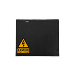
 Close-up of the IP68 rated waterproof surface showing the textured protective layer over the solar cells.
 Key features: 200W maximum power output, High-efficiency PERC solar cells, Optimised for low-light performance.
 Extremely low profile at only 2mm thick, providing an aerodynamic solution for vehicle mounting.


Regular price
$379.00
Availability:
In Stock
 View all products from Sunman
Guaranteed Safe and Secure Checkout
97
DESCRIPTION
Sunman eArc 200W Black Square Flexible Solar Panel - Compact and Efficient Mono-PERC Solar Panels - Junction Box Underneath
Superior solar technology with the newly improved, compact Mono-PERC solar panels. These lightweight yet robust panels are perfect for various applications, including caravans, motorhomes, yachts, trains, and buses.
Key Features:
- Lightweight and durable construction with cutting-edge technology
- Highly efficient monocrystalline cells for optimal energy production
- Flexible design for easy installation on various surfaces
- Endorsed by the Clean Energy Finance Corporation and Australian Renewable Energy Agency
- CEC-approved for residential and commercial use
- 10-year product warranty for buildings and 5 years for mobile applications
Crafted using a patent-pending composite material akin to airplane windows, Sunman solar panels offer unmatched durability. Approved by the Clean Energy Council for residential use, these panels are tough without the need for a heavy, rigid frame or glass. Explore the 'About Sunman' tab for more details.
Optional Mounting Solutions
Multiple mounting options available, ensuring a secure and efficient installation that meets your specific needs. Please carefully follow the mounting instructions here which include the below:
- Vented Gap Kit: Improves panel efficiency and reduces surface heating. Includes high bond double-sided adhesive tape and polycarbonate strips. (Height increase of approximately 15mm)
- High Bond Double-Sided Adhesive Tape: Provides a low-profile, secure bond for smooth surfaces. (2.3mmH x 12mmW x 16.5mL)
- Structural Silicone (Fix8): Can be used to adhere the panel to a surface.
Experience the difference of Sunman eArc solar panels for yourself, and join the countless satisfied customers who have made the switch to a more sustainable and efficient energy solution.
In some instances there may be slight manufacturing changes between batches. If you are adding to an existing array, please check with the sales team to review any variances.
SPECIFICATIONS
Specifications
| Model | SMF200J-6X10DB-Se | |||
| Solar cells | 40 (4x10) | |||
| Maximum Power (Pmax) | 200 | |||
| Maximum Power Voltage (Vmp) | 34.7 | |||
| Maximum Power Current (Imp) | 5.78 | |||
| Open-circuit Voltage (Voc) | 41.1 | |||
| Short-circuit Current (Isc) | 6.66 | |||
| Operating Temperature (°C) | -40 °C to 85 °C | |||
| Maximum System Voltage | 1000 V DC (IEC) | |||
| Maximum Series Fuse Rating | 20 A | |||
| Application Class | Class A | |||
| Power Tolerance | 0/+5 W | |||
| Backsheet | White | |||
| Junction box | IP 68 rated (each j-box has one by-pass diode) | |||
| Output Cables | Photovoltaic technology cable 4.0 mm2, (+)150 / (-)450 mm | |||
| Connector | MC4 compatible | |||
| Dimensions (L x W x H) | 1159 x 1026 x 2mm | |||
| Dimensions Incl JB (L x W x H) | 1159 x 1026 x 22mm | |||
| SKU: | eASMF200J-6X10DB-Se-1 |
| Model #: | eASMF200J-6X10DB-Se-1 |
| MPN: | eASMF200J-6X10DB-Se-1 |
| HS code: | 8541430010 |
| Country of origin: | CN |
| Package weight: | 3.9 kg |
| Package length: | 1.35 m |
| Package width: | 1 m |
| Package height: | 0.01 m |
WARRANTY
Warranty
1. Limited Product Warranty for Mobile/Marine Applications
Sunman (Zhenjiang) Company Limited (“SUNMAN”) warrants that its photovoltaic modules together with the DC connector cable assemblies are free from defects, if any, in materials and workmanship under normal application, use, installation and service conditions for a period of pending 60 months from the delivery (Incoterms 2010) of SUNMAN modules (“Modules”) to the original end customer (“Customer”), or 12 months after the date of production of the Modules as indicated in the serial number, whichever date is earlier.
If Modules become malfunction or inoperative due to defect in material or workmanship during such pending 60 months period set forth above, SUNMAN will, at its own option, either repair or replace the Modules in problem, or refund a reasonable portion of the purchase price as paid by the Customer (“Purchase Price”). The repair or replacement or refund remedy shall be the sole and exclusive remedy provided under this Limited Warranty.
2. Limited Peak Power Warranty and Limited Remedy
SUNMAN warrants the percentage of nominal power output as below:
- A solar Module’s performance warranty will typically guarantee 90% of rated power output at 5 years.
- SUNMAN warrants each Module against defects in materials and workmanship that result in the failure of the Modules to produce the warranted percentage specified above of the nominal power output for the Module set forth in SUNMAN's product datasheet.
If SUNMAN determines in its discretion that any Module is not providing the warranted percentage of the nominal power output due to Modules’ defects in material or workmanship attributed to SUNMAN, SUNMAN will, at its sole option and discretion, either:
- Make up such loss in power by providing to Customer additional Modules;
- Repair or replace the defective Modules including free shipping to the place supplied by SUNMAN; or
- Refund Customer such loss proportion arising from unqualified power output which less than the warranted percentage of the nominal power.
The remedies set forth in Section 2 are the sole and exclusive remedies provided under the limited minimum Peak Power Warranty.
3. Exclusions and Limitations
- Warranty claims, in any event, shall be filed in writing to SUNMAN or its authorized distributors within the applicable warranting period.
-
These Limited Warranties will not be applied to normal wear and tear, to the natural effects of exposure to weather conditions over time, or to the Modules which under SUNMAN's sole judgment have been subjected to:
- Misuse, abuse, neglect, vandalism or accident;
- Alteration, improper installation or application;
- Repair or modifications that do not strictly follow the manufacturer’s instructions;
- Non-observance of SUNMAN’s maintenance instructions;
- Power failure, electrical spikes or surges, lighting, flood, fire, accidental breakage or other events outside the control of SUNMAN.
- These Limited Warranties only cover the transportation costs for shipment of any repaired or replaced Modules to the place applied by SUNMAN. Any costs for returning the Modules to SUNMAN or its authorized agents and authorized distributors, or costs associated with installation, removal or reinstallation of the Modules, shall be borne by the end user Customers.
- Warranty claims will not be honoured if the type or serial number of SUNMAN Modules have been altered, removed or made illegible without written authorisation from SUNMAN.
4. Transferability
This warranty is extended to the original end-user purchaser, and is also transferable to any subsequent owner of the location or holder of the product when Module(s) remain at their original installed location upon satisfactory proof of succession or assignment.
5. Obtaining Warranty Performance
In order to obtain warranty service under the SUNMAN Limited Warranty, the end user Customer should promptly notify SUNMAN regional customer service centre.
Together with the notification, the complete serial number printed on the module label and the shipment date of its Modules shall be marked as well. If the Modules will be returned for inspection, repair or replacement by SUNMAN, SUNMAN will give the Customer a Return Merchandise Authorization (RMA). However, SUNMAN will not accept a return of any Modules without a RMA.
6. Disputes
No action, regardless of form, arising out of or in any way connected with this Limited Warranty, may be brought by the end user Customer more than one (1) year from the date when causes of action occurred.
7. Various
The repair or replacement of the Modules or the supply of additional Modules does not lead to a new commencement of warranty terms, nor shall the original terms of this Limited Warranty be extended. Any replaced Modules shall become the property of SUNMAN.
SUNMAN shall at its own options to deliver another type of PV Modules, different in size, colour, shape, or power, either a new brand or the original one, in case of that SUNMAN has discontinued producing the module in question at the time of the claim.
8. Force Majeure
SUNMAN shall not be in any way be responsible or liable to the end user Customer or any third-party arising out of any non-performance or delay in performance of any terms and conditions of sale, including this Limited Warranty, due to fire, flood, blizzard, hurricane, thunder, acts of God, changes of public policies, terrorism, war, riots, strikes, unavailability of suitable and sufficient labour or materials and other events which are out of control of SUNMAN.
Note
“Peak Power” is the power in watt peak that a PV-module generates in its maximum power point. SUNMAN measurements are as follows:
- Light spectrum of AM 1.5;
- An irradiation of 1,000W per m2; and
- A cell temperature of 25 degree Centigrade.
The measurements are carried out in accordance with IEC61215 as tested at the junction box terminals per the calibration and testing standards of SUNMAN valid at the date of manufacture of the PV-Modules. SUNMAN’s calibration standards shall be in compliance with the standards applied by international institutions accredited for this purpose.
WIRING INSTALLATION
SOLAR 4 RVS
OFF-GRID, EXTRA LOW VOLTAGE SOLAR PANEL WIRING GUIDE
Please read this document in full before commencing installation.
To maximise the efficiency and longevity of your new solar panels, please ensure you follow the instructions in this guide carefully. Failure to do so WILL result in shortened panel lifespan AND void your warranty.
While it seems simple to connect solar panels to your battery, common installations practices such as using non-waterproof connectors as permanent connection points CAN damage the solar panel AND void your warranty, please continue reading the guide for more details.
Whilst due care has been taken to ensure the recommended wiring practices will provide a safe and efficient installation, we cannot guarantee these methods will be suitable in every scenario due to variations in cable, connectors, solar charge controllers, environment, and installation practices. It is the duty of the installer to verify the installation is installed to local standards and refer to each manufacturer’s instructions.
This guide is limited to 12 and 24V battery systems.
Contents
Selecting an Appropriate Solar Panel based on the Specifications
Series, Parallel and Combination Wiring Installations
Installation Type 1 – Parallel Wiring
Installation Type 2 – Series Wiring
Installation Type 3 – Series/Parallel Combination Wiring
Paralleling and Series of Different Solar Panels
Bypass, Blocking Diodes and Shading
Sizing a Solar Charge Controller
Safety
- All work should be carried out in shade or inside out of direct sunlight. Use a towel or blanket on top of the panel to reduce light exposure;
-
 Work safely at heights. Ensure you have a sturdy, secure ladder;
- Use insulated tools;
- Ensure the panels are kept covered during installation;
- Wear appropriate footwear;
-
 Use gloves and other PPE where appropriate;
- Seek help where needed.
- This guide is only relevant for installations installed at below 120V DC using the Open Circuit Voltage (Voc) rating of the solar panel.
Example: Model Exo-SP-F4-200, the Voc is 24.1V, therefore 5 panels in series is 120.5V and would require a licensed electrician to complete an installation.
- Extra low voltage solar arrays CAN cause fires AND/OR injury/death if adequate precautions are not taken.
- Do not leave the solar panel short-circuited (i.e. the MC4 connectors should NOT be connected together) and exposed to the sun, this can cause failure of the bypass diodes, hot-spots and permanent damage to the solar panel within minutes.
Selecting an Appropriate Solar Panel based on the Specifications
 The wattage of the solar panel is calculated by Max Power Voltage (Vmp) x Max Power Current (Imp), i.e. 10.2A x 19.8V = 202W.
When no power is being drawn from the solar panel, the Voc will be present.
To charge a 12V battery bank, dependent on the charge controller, approximately 7V is required between the absorption voltage requirement of the battery and the solar panel Voc. I.e. a calcium 12V battery that requires 14.8V absorption voltage, will need a panel with at least 21.8Voc. Most solar panels are approx. 23Voc. When calculating the array current, use the short circuit current (Isc).
The diagram to the right shows a simple photovoltaic (PV) / solar array connected to a 12V battery.
Never install a solar panel in a permanently shaded location, this can damage the bypass diode and cause hot spots.
If a solar isolation switch is used, it should be sized to handle the full short circuit current of the array, plus ~20% to avoid nuisance tripping. I.e. if an array is rated to 30Asc, then the circuit breaker should be at least 36A, the closest match will be a 40A circuit breaker.
Series, Parallel and Combination Wiring Installations
When more than one solar panel is used, each solar panel can be connected to an individual solar charge controller, this will generally lead to the best performance but at the highest cost and complexity.
An alternative is to wire the panels in either series or parallel or a combination of both.
 Installation Type 1 – Parallel Wiring
This type of installation, most common for off-grid 12V systems, each solar panel positive is connected together, and each negative connected together. In this case, the array voltage will remain the same as a single solar panel, however the array current will increase.

If a solar panel were to fail by an internal fault, such as an internal bypass diode short circuit, the fault current of the array would all flow through the failed diode. There are many examples of this causing fires, string fusing has been designed to minimise the risk.
In the example (above) of three solar panels, if the left panel were to fail from a shorted bypass diode, the middle and right solar panels would each pass 10A into the left solar panel. Therefore, 20A would pass through the 15A fuse, and cause it to disconnect the failed solar panel from the array.
The fuses should be located close to 3 to 1 branch connector.
Fusing is not required when two or fewer solar panel are used because it is not possible for the fuse to reach the required tripping current.
Parallel arrays provide good tolerance to shade and keeps the voltage low, and thus safer.
Installation Type 2 – Series Wiring
 In this type of installation, commonly used in 24V systems, one solar panel positive is connected to the next solar panel negative. In this case, the array current will remain the same as a single solar panel, however the array voltage will increase. Typically, 24V systems require an open circuit array voltage of at least 36.6V.
Each group of panels wired in series is called a “string”.
The advantages of series wiring are:
- Reduced wiring cost
- Reduced power losses in cables
- Typically improved performance in MPPT solar charge controllers
The disadvantages are:
- Poor shade tolerance
- High voltage rated solar controllers often required
- Less safe
Installation Type 3 – Series/Parallel Combination Wiring
This type of installation, commonly used in larger systems, two or more solar panels are connected in series to make a string, and two or more strings are paralleled together. In this case, the array current AND the array voltage will increase.
A note on MC4 solar connectors, these types of connectors are waterproof, affordable, high voltage rated, are pre-installed on most solar panels and are usually disconnectable. The current rating is typically limited to approx. 30A when 6mm2 or larger PV1-F solar cable is used, therefore they would not be suitable for four 10A solar panels wired in parallel without overloading the connector. Series/parallel wiring arrangements are a good way to overcome this while still being able to use these types of connectors

The advantages of this type of system wiring are:
- Partially reduced wiring cost
- Partially reduced power losses in cables
- Typically improved performance in MPPT solar charge controllers
- Avoids the need of string fuses when less than two strings are paralleled
- Reasonable shade tolerance
The disadvantages are:
- High voltage rated solar controllers often required
Paralleling and Series of Different Solar Panels
Panels can typically be wired in parallel when the same type of solar cell and voltage is used. I.e. two solar panels using P-type mono-PERC cells and both 24Voc can be paralleled, but if a P-type mono-PERC cell and n-type IBC cell are paralleled, differing coefficients of performance will cause a mismatch in voltages, causing the higher voltage panel to be “dragged down” to the lower voltage panel and increasing the risk of panel failure. Consult your distributor for verification before paralleling different types of solar panels.
At the time of writing, the Exotronic PERC series of solar panels are all designed to use the exact same cell cut into 36 pieces and therefore the voltage and performance will be nearly identical, and will thus provide good performance when paralleled.
Panels can only be wired in series when the cell type and current are the same, this is quite rare. Therefore typically only the same solar panel make and model can be wired in series.
Example: 2x 200W Exotronic Solar fixed solar panels can be wired in series, and 2x 30W Exotronic fixed solar panels can be wired in series, and each string can be wired in parallel. But the 30W and 200W panel cannot be wired in series.
Cable Size
The most practical wire for solar panels is PV1-F solar cable, this cable is most common in 4mm2 and 6mm2. A very rough rule of thumb is for arrays of less than 20A can use 4mm2, and 20A or larger should use 6mm2. If a larger size is required, it is recommended to run two runs from the array to the solar controller. There is no harm in using larger size cable except for practicality and cost considerations.
PV1-F cable is highly UV resistant, durable, high voltage rated, designed to fit MC4 connectors, highly stranded, and tinned copper. It’s properties mean the cable is well suited for most applications including marine, and it is also cost effective.
Solar Array Performance
Solar panels are rated at Standard Test Conditions (STC), this means solar panels are placed on a bed of light rated at 1000W/m2 at 25C and at sea level. This is why it is not typical to see the solar panel output in typical conditions, combined with the other losses (dirt on panel, cable/connection losses, sun orientation, panel temperature, solar controller losses, battery efficiency losses) the actual output that will be seen will likely be much lower.
Often a rule of thumb is you will see up to 75% of the STC rating of the solar panel at midday in summer. I.e. 150W from a 200W solar panel.
In some rare cases you may see close to full output, i.e. the solar panel has been stored in a cool garage, and suddenly exposed to full midday summer sun. As the panel heats up, performance will drop to the more typical 75% output.
For the best performance, the solar panel should be perpendicular to the sun, however normally brackets to make the solar panel face the sun provide minimal performance improvement at a much higher complexity and cost.
Bypass, Blocking Diodes and Shading
 Each solar panel will have one or more bypass diodes. Despite the marketing claims, the main purpose of bypass diodes is to protect the cells from overheating. When a cell is shaded it causes the cell to increase resistance, as current flows through the resistance, the cell heats up, and if the current is not bypassed around the cell, it will cause a hot spot and subsequent failure of the cell, and as each cell is wired in series, failure of the whole solar panel.
In 12V arrays, the bypass diodes, while necessary for the purpose of protection of the cells, provide minimal performance improvement.

When a solar panel is completely shaded, it can become a resistance, causing the power flow of other solar panels to flow through it in reverse thus causing power loss in the system.
Blocking diodes can be installed to prevent this. However, this event is rare, and the diodes will cause power loss at all times. Therefore, unless specifically required by the manufacturer, blocking diodes should be avoided. Most good quality solar controllers should have their own blocking diode installed, and therefore an additional blocking diode is not necessary for single panel installations. They are also not a replacement for string fusing.
Sizing a Solar Charge Controller
The solar charge controller or solar regulator must be sized appropriately for the array. A too small charge controller can be damaged, and too large can be unnecessary.
If using a PWM controller, typically you must use a larger controller than required. You must also use a 30-36 cell (17 to 20Vmp) solar panel on a 12V battery or 60-72 cell (34 to 40Vmp) solar panel on a 24V battery. To size a PWM controller, a simple calculation is: Power of Array in Watts / Battery Bank Voltage x 0.8 for losses, i.e. 400W / 12V x 0.8 = 26.7A controller required.
If using an MPPT controller, you can often size the controller smaller to reduce costs, while still allowing maximum performance in winter. When using an MPPT, ideally use a 36 cell or more (19Vmp+ limited by the maximum input voltage rating of the PV input of the solar controller) solar panel on a 12V battery. To size an MPPT controller, a simple calculation is: Power of Array in Watts / Battery Bank Voltage x 0.8 for losses, i.e. 400W / 12V x 0.8 = 26.7A controller required. However you can often downsize to a 20 or 25A controller as it is often only in summer when the most power is available, that the controller will reach the maximum output, and therefore oversizing is not necessary.
MPPTs will have significantly improved performance when it is required the most, i.e. during the cooler months where there is more likely to be shading, and low light conditions.
Solar Panel Efficiency
 Solar cell efficiency is effectively how much light is converted to power in terms of m2 of the solar cell.
Solar panel efficiency is the same measurement, but takes into account the entire panel, i.e. the space between the cells and the frame. Therefore solar panel panels can be more efficient simply by decreasing the space between the cells, and to the frame. This is why larger solar panels are more efficient then smaller panels; less borders/gaps to cell ratio.
Practically speaking, when useable area is limited, a 22% efficient 300W solar panel could take up most of the available space, limiting the room for future panels and increasing the complexity of wiring, whereas it could be possible to install 2x 200W modules plus a 160W solar panel on a single controller, greatly increasing the total power of the array and keeping the wiring relatively simple. There are many different solar technologies, the most common is monocrystalline. While the highest cost, it is higher in efficiency compared to polycrystalline and amorphous, and therefore reduces the quantity of solar panels needed and simplifies the system. Amorphous, while having improved shade tolerance, is very low efficiency, therefore even when compared to a shaded monocrystalline module, the overall output can often be worse.
Cells get exponentially more expensive as the efficiency increases, the easiest way for unscrupulous retailers to increase profits is to overstate the rated output of the solar panel. In the example below, the solar panel is 18V and advertised to be 350W, therefore it should have an Imp of approximately 19.4A. The cells, based on the specifications and appearance are ¾ cut 156mm cells with 5 wire busbars. The highest output possible on cells of this nature is approximately 7.5A. Therefore it is not physically possible for this solar panel to exist. A true output of a panel this size will be approximately 120 to 130W based on several reasonable assumptions. As Sunpower uses interdigitated back contact cells, there are no busbars on the front, so the cells type stated below is also incorrect.

The highest cost and most efficient solar cells commercially available at the time of writing are approximately 24% efficient, and therefore the maximum efficiency for a very large module could approach 23% efficient.
Maintenance
To ensure your solar panels are performing optimally, be sure to keep on top of this simple maintenance checklist.
- Clean on a regular basis with neutral soap & clean water, using a soft sponge or cloth;
- If in a marine environment, wash regularly with fresh water to avoid damage caused by saltwater;
- Periodically inspect the mechanical and electrical connections;
- Denatured alcohol (methylated spirit) can be used to remove grease etc.
Ongoing Support
Solar 4 RVs are proud to offer a support service beyond the purchase of your solar panels. If you require further technical support, please feel free to contact us. We are happy to help!
MOUNTING INSTALLATION
FLEXIBLE SOLAR PANEL MOUNTING INSTRUCTION GUIDE
Please read this document in full before commencing installation.
To maximise the efficiency and longevity of your new solar panels, please ensure you follow the instructions in this guide carefully.
While it seems simple to mount a flexible solar panel, common installations such as sealing around the edges of the solar panel and direct adhesion of the solar panel to a surface using Sikaflex and most other adhesives may damage the solar panel and void your warranty, please continue reading the guide for more details.
Whilst due care has been taken to ensure these methods provide a secure and permanent mounting connection, we cannot guarantee these methods will be suitable in every scenario due to variations in substrate materials, environment, and installation technique and therefore we accept no liability for any failures caused, the installer is responsible for confirming that the panel, adhesive, mounting surface, mechanical retention, cable routing, and installation method are suitable for the vehicle, expected road conditions, wind exposure, heat exposure, and local legal requirements. It is the duty of the purchaser to regularly inspect and maintain the solar panel installation.
It is normal for solar panels to heat up to above 85°C in operation or higher in fault conditions. In some cases, this can damage the substrate. Solar 4 RVs will not be liable for any damage to the substrate the panels are installed onto. We recommend using a method that creates a gap between the substrate and the module for this reason, such as the 4.6mm thickness VHB tape for spacing.
If you need clarification on any of the instructions, please contact your distributor.
Contents
Protecting the panels during installation.
Safety.
Panel Curvature (Flexibility).
Handling the Panel.
INSTALLATION ONTO A RIGID SURFACE.
STEP 1 Clean and degrease the surface area.
STEP 2 Mark the position of panels accurately.
STEP 3 Mount the panels using one of the following methods.
Method 1 – Vented Gap Kit (Sunman eArc panels with Junction Box Underneath ONLY).
Method 2 – Solar 4 RVs 2.3mm or 4.6mm High Bond Tape or 3M 2.3mm 4991 Tape.
Method 3 – Silicone Based Adhesives.
Method 4 – Onto Checker Plate (or other highly textured surfaces).
INSTALLATION ONTO ROOF RACKS.
INSTALLATION ONTO CANVAS.
Method 1 – Zippers.
Method 2 – Velcro (hook & loop).
Method 3 – Eyelets.
Example of good installs.
Example of bad installs.
Maintenance.
Pre-Installation Checklist.
Ongoing Support.
Protecting the panels during installation
IMPORTANT:
- All work should be carried out in shade or inside out of direct sunlight. Use a towel or blanket on top of the panel to reduce light exposure;
- Do not install the panels in windy or gusty conditions. Damage may result when handling or carrying a panel, or a gusty wind may lift and carry a lightweight panel;
- Do not damage the top layers or underside surfaces as the performance and longevity of the PV panel may be reduced if the surfaces are damaged;
- Do not store/stack other items underneath or on top of the panels;
- Avoid wearing sharp rings and jewellery during the installation;
- Avoid over-flexing the panels or repeatedly flexing the panel;
- Avoid installing on a sunny day as adhesive/sealant can cure too quickly or surfaces, tools and the panel can become too hot for normal handling;
- Ensure the panels are fully supported, especially in the sun. A partially supported panel will get a permanent line crease between the supported and unsupported parts of the panel;
- If sharp or heavy objects are allowed to fall onto the panels, they can cause fractures in the cells;
Safety
- Work safely at heights. Ensure you have a sturdy, secure ladder;
- Use insulated tools;
- Ensure the panels are kept covered during installation;

- Wear appropriate footwear;
- Use gloves and other PPE where appropriate;
- Seek help where needed.
Panel Curvature (Flexibility)
The panel can be curved with a gentle radius to a maximum mid-point deflection of approximately 100mm over a length of 1.5m.

There can only be one axis of bending in a panel; Longitudinal OR Transverse.
Longitudinal axis
The longitudinal bend can be convex as shown below.

Transverse axis
The image below shows a panel with multiple radii with all axis of rotation having the same direction, i.e. transverse with respect to the panel.

A real example of this is shown below

Multiple direction of axis
Panels cannot accommodate multiple radii with different directions without being stressed. For example, a longitudinal bend and a transverse bend.

Handling the Panel
Do not bend the panel excessively or repeatedly:
- The panels must not be bent more than 30 degrees per metre length, otherwise the cells and cell interconnections will be stressed;
- When being laid down both sides of the panel must be supported, either by sliding the panel along the surface or by having one person support each side;
- Panels must not be laid on a surface with one or both ends hanging over an edge. The whole panel should be supported.
Do not stress the cells or junction box during handling
- Avoid carrying panels larger than 60W horizontally (like a tray) as they will droop;
- Carry the panel vertically along the long/side edge by gripping the panel along the edge white area of the panel (not putting pressure on the cells);
- Be careful not to apply excess pressure when holding the panel along the edge cells – being on the edge there is less support for these cells;
- Do not create localised stress on the cells between thumb and fingers which could cause fracturing of the cells;
- When lifting or laying the panel down, slide the far edge of the panel over the surface so that the panel is supported by your hands and the surface;
- The junction box and cables are not handles – do not hold the weight of the panel via the junction box.
Important: Do not install if the mounting surface is unstable, damaged, flexible in multiple directions, heat-sensitive, poorly drained, contaminated, flaking, painted with weak coating, or unable to support the panel continuously.
A poorly installed panel may detach during travel and create a serious road hazard. Do not drive the vehicle until the installer has confirmed the mounting system has achieved adequate bond strength and mechanical security for the intended use.
INSTALLATION ONTO A RIGID SURFACE
If mounting your panel(s) onto a rigid surface such as an RV roof, you will need to take into consideration the thermal expansion and contraction of both the panel, the surface it’s being mounted to and the product used to adhere the two together. It is unlikely both the panel and surface will expand and contract at the same rate, therefore an adhesive with some ‘give’ will be required to absorb the difference.
UNSUITABLE Adhesive Products
- Polyurethane adhesives (i.e. Sikaflex)
- MS Polymer (i.e. Fix15)
SUITABLE Adhesive Products
- Combination of suitable* high bond double sided tape and Silicone based adhesives (i.e. SG20, Fix8)
- Silicone based adhesives (i.e. SG20, Fix8)
*Suitable means, confirmed via the manufacturer, Solar 4 RVs, or local standards, and verified compatible to the substrate by the installer. Suitability still depends on substrate condition, preparation, temperature, installation technique, load, and use environment.
You will also need to consider if the mounting surface is suitable for the purpose.
UNSUITABLE Mounting Surfaces
- Twin-wall polycarbonate sheet
- Corflute
- High Density Polyethylene (HDPE, Kingboard®, Seaboard®, Boatboard®, etc.)
- Any other surface that is unstable, damaged, or may be damaged by high temperatures, mechanical stress or trapped moisture.
SUITABLE Mounting Surface: (using an approved mounting method)
- Aluminium
- Steel
- Sealed Marine Plywood
- Fibre-glass
- Checker plate*
STEP 1 Clean and degrease the surface area
To ensure proper adhesion, all surfaces (mounting surface, back of panel and strips if being used) must be cleaned and degreased. Not doing so will weaken the bond and can cause the bond to fail.
- Clean the surfaces with slightly soapy water to remove excess grime/dirt.
- Check the surface for any loose paint or blemishes, if required rub the mounting surface with a fine or medium grit emery.
- Use a suitable degreasing product such as industrial alcohol or isopropyl alcohol.


STEP 2 Mark the position of panels accurately
Check measurements and if needed, mark the position of the panels ensuring there is no overlap.

STEP 3 Mount the panels using one of the following methods
Method 1 – Vented Gap Kit (Sunman eArc panels ONLY)
The Vented Gap Kit is available exclusively from Solar 4 RVs and consists of pre-cut strips of twin-wall polycarbonate sheeting & VHB Tape.
How To:
Lay the panel face down on a soft surface (carpet, towel, etc.) and then line the strips into position. The strips have been pre-cut to fit along the width of the panel and should be positioned so that each strip runs in between each row of cells (approx. 160mm) with the exception of the ends of the panel which have 2 strips each. Use a pencil or pen to mark where the strips will sit.
NOTE: Now that many panels use cut cells, the spacing may need to be every 2 or 3 cut cells to make the approx. 160mm distance. Normally panels 175W to 215W will use 12 strips, 4 at the ends, the 8 distributed along the middle. 100W panels will use 9 strips.

Top of panel with ‘Junction Box Under’ - Position strips around the junction box. Different panels will have slightly different junction boxes, but the principle remains the same.

Top of panel with ‘Junction Box on Top’ – Position 2 strips at the top, then 1 strip every cell gap width for the remainder of the panel.
 Bottom of panel (regardless of junction box position).

Side view of panel with panel, showing double strips at top.
If your panel has the Junction Box on Top - Apply double-sided acrylic high bond foam tape to both sides of the strips and attach to the panel (leave the top layer of red plastic intact for now). Finger pressure must be used to push the tape into the surface to make sure that it has sufficient grip on the surface for adequate bond strength.
If your panel has the Junction Box Under - Apply double-sided acrylic high bond foam tape to both sides of the strips. You will need to use extra layers of tape to build up the area in which the junction box sits. Do this by applying up to 2 layers of tape on each side of the strip (4 layers of tape total per strip near the junction box). The tape will bond together. Once done, attach the strips to the panel (leave the top layer of red plastic intact for now).

Double layer of tape.
Once the strips are attached to the panel, proceed to carefully lay the panel into position and remove the red plastic layer. Gently apply pressure in between the cells, along the strips, ideally with a roller. Ensure you do not apply excessive force or push on the cells where there is no strip behind as this will damage the cell.
Wait time of tape to full strength:
20 minutes – 50% strength
1 hour – 75% strength
1 day – 90% strength
3 days – 100% strength
Apply silicone-based adhesive at the end of each strip:
The silicone must adhere to the solar panel and substrate with a minimum 15 mm² contact area at the end of each strip.
Method 2 – Solar 4 RVs 2.3mm or 4.6mm High Bond Tape or 3M 2.3mm 4991 Tape
Both above-mentioned tapes have been tested by Solar 4 RVs and deemed suitable for use in mounting our solar panels. Any other brand of tape should not be used unless prior approval has been given.
Follow the instructions in Method 1, ignoring any mention of the plastic strips.
Method 3 – Silicone Based Adhesives
If using a Silicone based adhesive such as SG20 or Fix8, apply the product in strips running the width of the panel underneath each cell gap or no more than approx. 180mm apart using lines of minimum 15 mm² contact area.
Do not seal around the edge of the panel as this will trap air under the panel which will expand as the panel heats up, causing damage to both the panel & mounting surface.
A roller may be used gently to apply pressure to the adhesive, however it is required to create a gap of 2-5mm between the panel and the substrate, therefore a spacer must be used which should be removed after adhesion, alternatively use the 2.3mm or 4.6mm tape in addition to the adhesive to create a permanent even spacer.

Method 4 – Onto Checker Plate (or other highly textured surfaces)
High bond tape does not bond well to checker plate. Some adhesives may appear to bond well at the start but then lose adhesion over time. For these reasons, we recommend that another medium such as aluminium composite (as a sheet or cut into strips) be used in between the checker plate and tape. Attach the aluminium to the checker plate with screws, pot rivets or a suitable adhesive then use of one of our standard mounting methods to mount the panel to the aluminium.


The bond area of the roof should be well drained, i.e. panels should not be bonded where water can puddle. Any droops in the surface should be fixed first.
Other textured surfaces may not be suitable for tape and require the use of this method.
INSTALLATION ONTO ROOF RACKS
If mounting on a roof rack where there is no way to support the edge of the panel, Sunman eArc panels can be stiffened by the use of C channel to the edges, and flat bar between the front and back of the panel, this additionally provides edge protection on the front and rear ends of the panel.


The flat bar is fixed to the panel using appropriate very high bond tape – if required the bar can protrude past the panel to line up with the roof racks to avoid the need to drill through the panel. The C channel slots onto the panel and flat bar and it is secured using Fix8 injected into the C channel.
The panel can be fixed to the roof rack using bolts and/or screws on the exposed aluminium section. Alternatively eyelets can be fitted at the point of sale for fixing.
INSTALLATION ONTO CANVAS
Panels can be attached to canvas providing the following guidelines are carefully adhered to:
- The canvas must provide continuous support to the panel
- Shallow radius, i.e. do not bend panel excessively
- The panel is not laid over irregularities such as structural elements, e.g. ridges/beams/tubes. These will result in the panel creasing over the structure causing premature failure.
- Panels shall not be placed over tubes supporting the canvas
- The canvas shall provide continuous support for the panel
- No part of the installed panel shall be bent by more than 10 degrees per metre length
- Panels shall not be placed onto a canvas surface where there are multiple radii with
- different axes.
- The canvas shall be kept taut
- No part of the panel shall be covered with any form of transparent material
Method 1 – Zippers
Zippers along each long edge can be used. These are sewn under the panel so that the zip material provides a cushion against the edge of the panel.

This image demonstrates the zipper method along with good execution of a cover over the edge of panel and zip.
A canvas maker’s standard industrial machine is adequate to sew zips onto the panel. You will need to provide the following instructions to your canvas maker:
- Use a YKK Marine rated zipper, UV resistant with auto locking slider
- Use a coarse stitch of at most 5-6 threads per inch
- Use polyester or PTFE based thread
- Attach zips in opposite directions so the sliders are at opposite corners of the panel
Method 2 – Velcro (hook & loop)
Marine grade stitched UV resistant Velcro must be attached under and over the panel so that the panel is in the “middle of a Velcro sandwich”. Velcro is not recommended as on removal of the panel, excessive force may damage the cells compared to zips, where less force is applied to the cells during removal.


Method 3 – Eyelets
Solar 4 RVs can punch stainless steel eyelets into the panel at various intervals (please advise at time of purchase) along the panel. Rope or similar material can then be used to tie the panel down to a supported surface.
Enough eyelets must be attached alongside each panel edge to fully support the panel. The size of panel will determine the adequate number of eyelets. Speak to our technicians to confirm based on the panel you’ve purchased.

Combination of eyelets & Rope.

Combination of eyelets, rope & rope clamp.
Example of good installs

o Panels are well supported by the canvas over the entire back surface of the panel
o Panels are well clear of the transverse beams
o Slight bending of panel in one axis
o Similar sun strength on all cells and panels as curvature is slight
o Cables are not applying any lifting, shear or twisting force on the junction box, i.e.
o Cables are laid neatly, level and are gently radiused.
o Custom “sewn-in conduit” keeps cables neat

o End of panel is well clear of the sharp roll-off at the side of the bimini
o Canvas is taut which is essential to avoid “flapping” induced mechanical stress on the panel

o Custom pocket houses a polycarbonate enclosure containing 3 fuses
o Underside location avoids rain/seawater directly on the IP67 solar connectors
o Panels can be easily removed as connectors are used
Example of bad installs

o Panels have an obvious crease which will cause stress on the cells
o Plastic cover over panels traps excess heat and moisture
In this example, the bending over the tube led to fracturing of the cells and produced a hot spot within months of installation.


x Panels have an obvious crease which will cause stress on the cells
x Panels are flexing in multiple directions causing increased stress on the cells
Maintenance Schedule
Inspect the solar panel installation:
- After the first trip
- After the first month
- At least every 12 months thereafter
- After off-road travel, storms, extreme heat, roof cleaning, impact, or any event that may affect the installation
During each inspection, check for:
- Lifting edges, loose tape, failed adhesive, or movement of the panel
- Cracks, creases, delamination, bubbling, discolouration, or hot spots
- Water pooling under or around the panel
- Damage to the roof or mounting substrate
- Cable movement, rubbing, sharp bends, or strain on the junction box
- Loose, corroded, dirty, or damaged connectors
- Dirt, salt, sap, bird droppings, or debris on the panel surface
- Corrosion of brackets, attachment points, substrate or panel
Clean the panel regularly using clean water, neutral soap, and a soft sponge or cloth. Do not use harsh chemicals, abrasive pads, pressure washers, or solvents unless specifically approved.
In marine, coastal, dusty, or high-salt environments, wash the panel and connectors more frequently with fresh water to reduce salt and contaminant build up.
Do not continue using the panel if it shows signs of mechanical damage, electrical damage, lifting, overheating, or unsafe cable strain. Rectify the issue before further travel or operation.
Pre-Installation Checklist
Before installing the solar panel, confirm:
- The correct panel model and installation guide have been checked.
- The panel has been inspected for damage before installation.
- The installer has confirmed the adhesive/tape cure time and will not drive the vehicle before adequate bond strength has been achieved.
- The mounting surface is rigid, stable, clean, dry, and suitable for the installation method.
- The mounting surface is not damaged, unstable, heat-sensitive, poorly drained, or likely to trap moisture.
- The mounting surface and back of the panel have been cleaned and degreased.
- The adhesive, tape, or mounting system is compatible with both the panel and mounting surface.
- The panel will be fully supported and will not be installed over gaps, ridges, tubes, sharp edges, or unsupported areas.
- The panel will not be bent beyond the limits stated in this guide.
- The panel will not be sealed around the edges.
- Full-surface adhesive bonding will not be used.
- Cables will be routed without pulling, twisting, rubbing, or placing strain on the junction box.
- Cable entry points and connectors will be protected from water ingress and mechanical damage.
- The installer has considered wind load, road vibration, heat exposure, roof curvature, and expected use conditions.
- The installation method complies with applicable laws, regulations, and vehicle/manufacturer requirements.
- Photos will be taken before, during, and after installation for future reference.
Ongoing Support
Solar 4 RVs is proud to offer a support service beyond the purchase of your solar panels. If you require further technical support, please feel free to contact us. We are happy to help!