Solar
 Solar Panels
 Solar Charge Controllers
 Mounting
 Solar Accessories
 Solar Kits
 Batteries
 Batteries
 Battery Management
 Battery Boxes
 Battery Kits
 Chargers
 Mains Chargers
 DC-DC Chargers
 Alternators & Regulators
 Charger Kits
 Inverters
 Inverters
 Inverter Kits
 Electrical
 Circuit Protection
 Connectors, Busbars & Terminals
 Switch Panels & Accessories
 240V Equipment
 EV Chargers
 Cables
 Cables
 Pre-made Leads
 Cable Management
 Converters
 DC-DC Converters
 Transformers
 Monitoring
 Monitoring
 Monitoring Kits
 Kits
 Pre-Wired Boards
 4x4/Canopy Power Systems
 Solar Kits
 Inverter Kits
 Charger Kits
 Battery Kits
 Monitoring Kits
 By Application
 Caravan, Camper & RV
 Camping & Portable
 Marine/ Boat
 4x4/4WD & Off-Road
 Off-Grid Homes & Sheds
 Golf Carts
 Portable 12V Car Chargers
 Portable 24V Bus/Truck Chargers
 By Brand
































 Pre-Wired Boards
 4x4/Canopy Power Systems
 Solar Kits
 Inverter Kits
 Charger Kits
 Battery Kits
 Monitoring Kits







































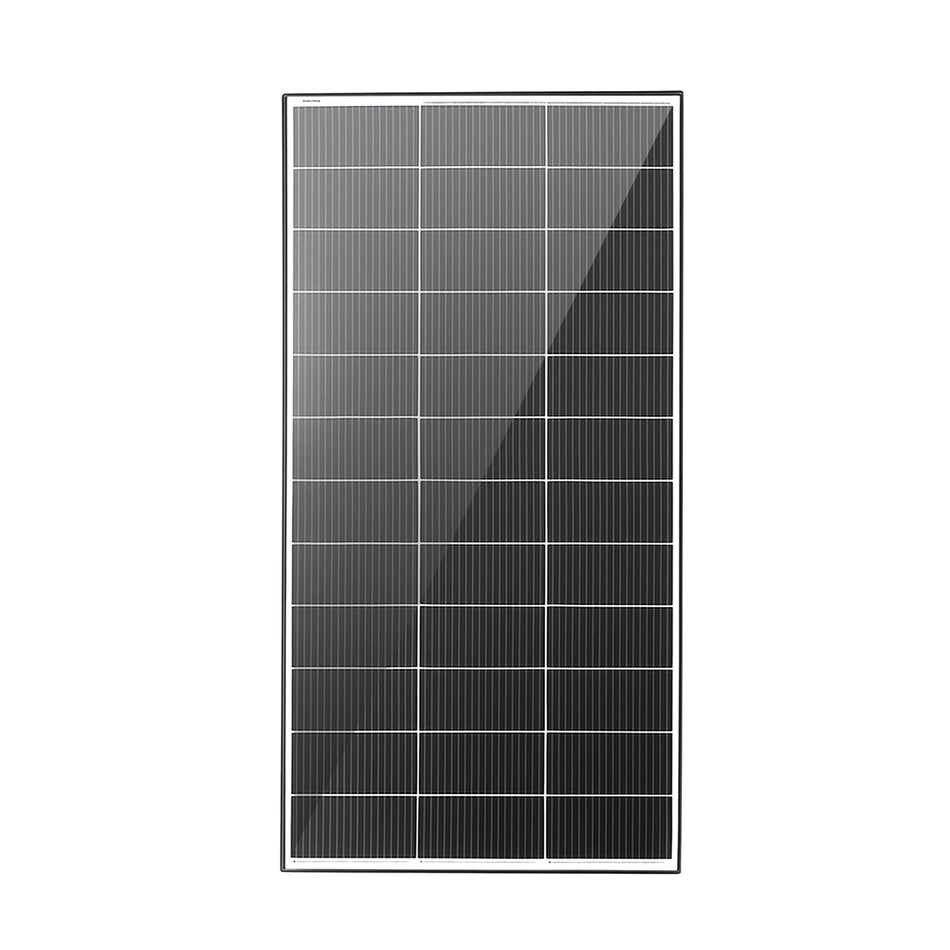
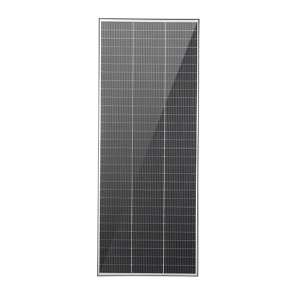
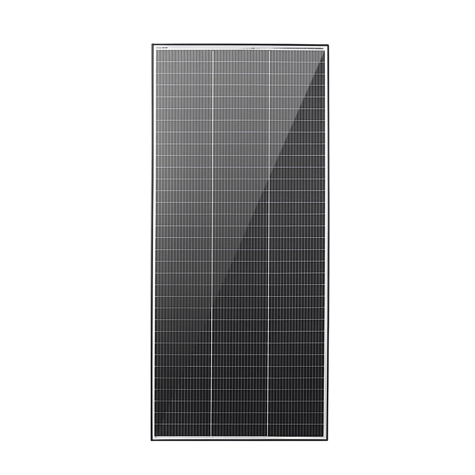
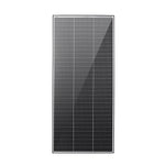
Exotronic 220W Fusion Fixed Solar Panel | Shade Resistant
Exotronic 220W Fusion Fixed Solar Panel | Shade Resistant
25.2% Efficient TOPCon Cells - 1470x670x25mm Black Frame


 Black anodised aluminium alloy frame provides structural strength and corrosion resistance.
 Highlights:IP68 Junction Box: Waterproof IP68 rated junction box,MC4 Compatible Connectors: Standard connectors for easy installation,Solar Cable: Durable UV-resistant solar cable,Aluminium Frame: Black anodised frame for mounting.

 Key features: Up to 20% smaller footprint, 25.2% higher conversion efficiency, -0.29%/C lower temperature coefficient.


Regular price
$251.10
$279.00
Availability:
In Stock
 View all products from Exotronic
Guaranteed Safe and Secure Checkout
773
DESCRIPTION
Exotronic 220W Fusion Series: Compact N-Type TOPCon Solar Panel for Off-Grid and Mobile Energy
High-Efficiency 12V Solar Panel — Designed for Caravans, RVs, and Marine Environments
The Exotronic 220W Fusion Series combines advanced N-Type TOPCon solar cell technology with a compact, lightweight design, making it an excellent choice for mobile and off-grid energy needs. With a fixed 25.2% cell efficiency, this panel outperforms many conventional monocrystalline solar panels and PERC modules—delivering reliable output even in limited space.
Engineered for use in 12V solar panel systems, it’s particularly well suited to caravan solar panels, camper trailers, boats, and other mobile setups. Whether you're planning a weekend getaway or installing a permanent caravan solar system, the Fusion Series ensures consistent performance across a range of conditions.
Triple Shade Resistance with Independent Parallel Strings
One of the standout features of the 220W Fusion Series is its intelligent string layout. The panel is built with three independent cell strings connected in parallel across the panel’s width. This architecture provides triple shade resistance: if one section is shaded, the remaining strings continue to produce power with minimal loss. This makes it ideal for environments where partial shading—such as from roof fixtures, awnings, or nearby
objects—is common.
TOPCon: Advanced Solar Technology
TOPCon (Tunnel Oxide Passivated Contact) represents the latest advancement in solar cell technology, delivering higher efficiency, reduced degradation, and improved low-light performance. It marks a clear upgrade over PERC solar panels, which themselves are more efficient than traditional monocrystalline cells. The Fusion Series’ N-Type TOPCon cells ensure consistent, durable energy output, ideal for varied weather and shading conditions typical of mobile and off-grid environments.
Why Choose N-Type TOPCon?
At the heart of this panel is a next-generation Tunnel Oxide Passivated Contact (TOPCon) structure, built on an N-Type base. This delivers superior stability, lower degradation over time, and better low-light performance compared to older P-Type and traditional monocrystalline solar panels—benefits that are especially valuable in Australia’s varied climates.
Combined with a 18-wire busbar design that reduces resistive losses and prevents hot spots, the result is a high-performance solar panel that keeps delivering, year after year.
- 25.2% cell efficiency for maximum energy density in a compact footprint
- N-Type cells for lower degradation and longer lifespan
- Excellent low-light response — ideal for cloudy days and shaded environments
- 18-busbar layout improves reliability and current flow across the cell surface
- Lightweight design — easier to install and handle, especially on vehicles and tight spaces
Durability You Can Depend On
The Fusion Series features a robust yet lightweight construction, making it ideal for use in caravans, RVs, and marine vessels. Designed to withstand Australian conditions, its 25 mm anodised aluminium frame ensures structural integrity without excess weight. The high-transmissivity, low-iron tempered glass enhances light capture and impact resistance.
- Salt mist and ammonia resistant – ideal for marine solar panels and coastal environments
- Rated for wind loads up to 2400 Pa and snow loads up to 5400 Pa
- Supplied with an 800 mm fly lead for quick, flexible installation
- Fully potted junction box prevents moisture ingress, ensuring reliable electrical connections and enhanced longevity even in harsh coastal and marine environments.
Versatile Applications — From Caravans to DIY Projects
Whether you’re upgrading an existing caravan solar panel setup, powering a remote shed, or exploring a DIY energy project, the Exotronic 220W Fusion Series offers a reliable and efficient solution. It’s especially well suited to:
- Charging 12V batteries in caravans, RVs, and boats
- Series wiring for 24V or 48V battery banks in off-grid setups
- Industrial off-grid projects where efficiency and weight are critical
- Remote off-grid installations like sheds, tiny homes, or remote workstations
- Supporting small-scale power systems for lighting, security cameras, and sensors
- Use in education, prototyping, or portable solar kits
With its compact footprint, durable construction, and proven efficiency, the Exotronic 220W Fusion Series is a compelling option among today's best solar panels for mobile and off-grid use. Whether you want solar panels for your next adventure or purchase solar panels for a fixed installation, this model delivers impressive performance in a smaller package—ideal for those seeking top rated solar panels without unnecessary bulk.
Ready to Go Off-Grid?
Order the Exotronic 220W Fusion Series today and experience high-efficiency solar technology that’s built for Australian conditions. Whether you're outfitting your caravan, boat, or tiny home, this panel delivers dependable power—wherever the road takes you.
SKU: Exo-SP-TCN-220
SPECIFICATIONS
Specifications
Electrical Characteristics | |||||||||
| Model | Power (W) | Dimensions (mm) | Weight (kg) | Vmp (V) | Imp (A) | Voc (V) | Isc (A) | ||
| Exo-SP-TCN-220 | 220 | 1470x670x25 | 10 | 19.8 | 11.11 | 23.1 | 12.1 | ||
Temperature Ratings | |
| NMOT | 41C +/-3C |
| Temperature Coefficient of Pmax | -0.37%/C |
| Temperature Coefficient of Voc | -0.29%/C |
| Temperature Coefficient of Isc | 0.05%/C |
Maximum Ratings | |
| Operating Temperature | -40 - +85C |
| Maximum System Voltage | 1000VDC |
| Maximum Fuse Rated Current | 15A |
Mechanical Characteristics | |
| Front | 3.2mm Tempered Glass |
| Frame | Black Anodized Aluminium Alloy |
| Junction Box | IP68 |
| Connectors | MC4 Compatible |
| SKU: | Exo-SP-TCN-220 |
| Barcode: | 9361784002590 |
| Model #: | Exo-SP-TCN-220 |
| MPN: | Exo-SP-TCN-220 |
| HS code: | 8541430010 |
| Country of origin: | CN |
| Package weight: | 11.0 kg |
| Package length: | 1.5 m |
| Package width: | 0.67 m |
| Package height: | 0.03 m |
WARRANTY
Exotronic Warranty Policy
This warranty policy applies to Exotronic products sold in Australia through authorised dealers and resellers. It applies to the original end-user purchaser of the product, as evidenced by the authorised dealer’s invoice, and is not transferable without Exotronic’s consent. Exotronic warrants that its products are free from defects in materials and workmanship under normal use and service, subject to the terms and conditions below. The benefits given by this warranty are in addition to other rights and remedies under law. Our goods come with guarantees that cannot be excluded under the Australian Consumer Law. You are entitled to a replacement or refund for a major failure and compensation for any other reasonably foreseeable loss or damage. You are also entitled to have the goods repaired or replaced if the goods fail to be of acceptable quality and the failure does not amount to a major failure.
Warranty Coverage and Periods
Covered Products: This warranty covers Exotronic glass solar panels, lithium iron phosphate (LiFePO4) batteries, pre-wired boards that may include several components such as inverters and chargers, and related accessories (such as electronics, cables, fuses, mounting hardware, and other ancillary items). The warranty periods for these products are as follows:
- Solar Panels: Exotronic solar panels are warranted for 60 months from the date of the authorised dealer’s invoice to the original purchaser for panels used in mobile or marine applications. When an Exotronic solar panel is used in a fixed installation such as a permanent building, the warranty period is extended to 120 months under the same terms. This warranty covers defects in workmanship and materials, ensuring the panels will operate as intended in normal conditions during the warranty period.
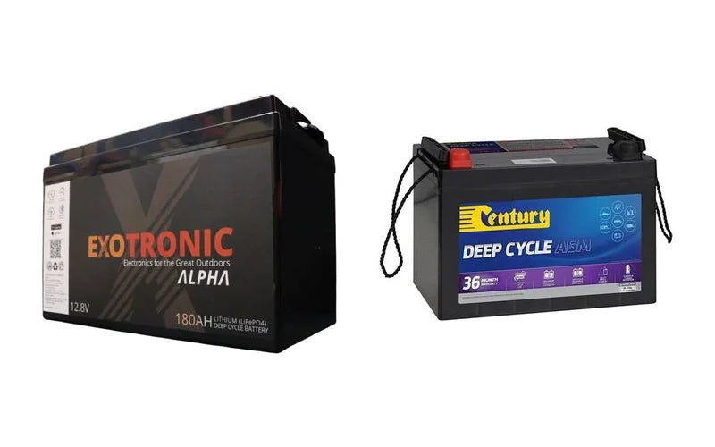
- Lithium Batteries: Exotronic LiFePO4 deep-cycle batteries are warranted for 60 months from the date of the authorised dealer’s invoice to the original purchaser. Exotronic guarantees that during this period, the battery will remain free of manufacturing defects and, when tested at Exotronic’s specified test conditions, will retain at least 80% of its original rated capacity under normal recommended use. This 5-year warranty for batteries is applicable to typical mobile and marine usage and is subject to a maximum of 3,000 charge/discharge cycles over the period. Exotronic batteries used beyond 3,000 full cycles or outside normal operating conditions may fall outside warranty coverage.
- Pre-Wired Power Boards and Integrated Assemblies: Exotronic pre-wired power boards and integrated assemblies (including boards supplied with pre-installed inverters, chargers, regulators, fuses, circuit breakers, and associated wiring) are warranted for 60 months from the date of the authorised dealer’s invoice to the original purchaser. This warranty covers defects in workmanship, wiring, assembly, and integration of components within the board under normal recommended use. Individual components supplied within the assembly may also be subject to their respective manufacturer warranties where applicable. This warranty does not extend to system performance beyond the board itself or to installation into a vehicle, vessel, or building.
- Accessories: Exotronic accessories and ancillary components (including but not limited to wiring kits, connectors, regulators, monitors, canvas bags, fuses, mounting brackets, and other electronic accessories) are warranted for 12 months from the date of the authorised dealer’s invoice to the original purchaser. This warranty ensures accessories will be free from defects in materials and workmanship under normal use for that period.
Commencement of Warranty: The warranty periods above begin on the date of purchase by the original end-user as shown on the authorised dealer’s invoice. In all cases, a valid proof of purchase from an authorised Exotronic dealer is required to claim warranty service.
Installer Responsibilities and System Design
Exotronic does not provide installation services and does not supervise or control installation practices. The purchaser and installer are solely responsible for installation design, location, and access provisions.
Exotronic products must be installed, integrated, and operated correctly to perform as intended. When installed into a broader electrical system, vehicle, vessel, or building, the product forms a component of that overall system. The installer, which may be the authorised dealer or a third-party professional, is solely responsible for ensuring proper installation and overall system design. Any issues or damage arising from incorrect installation, integration, or system design are not product defects and are not covered by this warranty. Exotronic will not be liable for inadequate performance or failures that result from the installer’s or designer’s actions or omissions. Key responsibilities of the installer/integrator include, but are not limited to:
- Appropriate Installation: All Exotronic products must be installed in accordance with Exotronic’s instructions, user manuals, any applicable electrical standards and industry best practices. Installations should comply with relevant Australian Standards and safety regulations for solar, marine, and automotive electrical work. The installer must ensure that the product is used in an appropriate environment and within its specified ratings. Improper or sub-standard installation practices may void the warranty, and installers are expected to exercise due care and professional skill in fitting Exotronic products.
- System Compatibility: The installer/integrator is responsible for selecting and using compatible components in the system. Exotronic solar panels, batteries, and accessories should be matched with appropriate chargers, controllers, inverters, and other equipment. If an Exotronic product is used with incompatible or improperly configured equipment, any resulting damage or underperformance is the responsibility of the installer and not covered by this warranty. It is expected that system designers will account for proper component sizing, load management, and environmental considerations.
- System Wide Performance: Overall system performance depends on design and usage factors beyond the product itself. The installer and end-user are responsible for ensuring the system as a whole is fit for purpose. This warranty assures the quality of individual Exotronic products only and does not guarantee the performance of the overall system into which the product is integrated. Issues such as insufficient power generation, rapid battery depletion, or other performance shortfalls due to incorrect system design are outside the scope of this warranty.
- Installation Location and Substrate Safety: The installer/integrator must ensure Exotronic goods are mounted and located in a manner that minimises the risk of damage to surrounding structures and materials in the event of a fault, overheating, arcing, or component failure. This includes ensuring suitable separation, ventilation, and mounting methods appropriate to the installation environment. For example, solar panels and power equipment must not be installed directly onto substrates or surfaces where heat transfer, adhesion, or mechanical fixation could cause damage to the substrate during a fault condition. Electrical and electronic equipment must not be mounted on flammable or heat-sensitive materials unless appropriate barriers, clearances, and protections are provided in accordance with applicable standards and best practice. Damage to surrounding structures, substrates, or materials caused by installation location, mounting method, inadequate separation, or inadequate fire/heat protection is not a manufacturing defect and is not covered by this warranty.
- System Protection and Fault Isolation: The installer must incorporate adequate protective devices such as but not limited to appropriately sized fuses, circuit breakers, low voltage protection circuits, alarms, and isolators where appropriate into the overall system design. It is the installer's responsibility to ensure components are adequately protected from one another so that a fault or failure in one piece of equipment does not cause cascading damage to other components. Damage to Exotronic products resulting from a lack of adequate system protection or improper fault isolation is not covered by this warranty.
Service Accessibility Requirement: Products must be installed in a manner that allows reasonable access for inspection, testing, servicing, and replacement. Exotronic is not responsible for additional labour, structural modification, access equipment, or other costs arising from installation methods that restrict reasonable service access to the product.
By installing the product, the installer acknowledges these responsibilities. Exotronic may require documentation of the installation such as wiring diagrams, photos, and details of connected equipment when assessing warranty claims to verify that the product was integrated properly. Installations not carried out by competent persons or not in accordance with Exotronic guidelines may void or limit the warranty coverage. Any advice provided by Exotronic in relation to system design is general in nature; ultimate responsibility for design and installation rests with the installer/integrator.
Independence of Dealers and Installers: Authorised dealers, resellers, and installers act independently and are not agents, employees, or representatives of Exotronic unless expressly agreed in writing. Exotronic is not responsible for the acts, omissions, or workmanship of independent dealers or installers.
Warranty Exclusions
This warranty covers manufacturing defects or failures of the product arising from normal use in compliance with Exotronic’s instructions. It does not cover any failure, damage, or performance issue caused wholly or partly by any external factors or by misuse of the product.
Warranty Exclusions Include:
- Improper Installation or Handling: Any damage or malfunction caused by incorrect installation, incorrect wiring, failure to follow the product’s installation manual, or failure to adhere to applicable installation standards is not covered. This includes but is not limited to damage from overtightening screws, improper mounting, insufficient support or ventilation, use of incorrect tools or improper connections. Damage or faults introduced during or due to removal and reinstallation of a product except when explicitly instructed by Exotronic for a warranty process, are also excluded unless it is unsafe to leave it in place.
- Misuse or Abuse: Use of the product for purposes or in modes it was not intended for, or in a manner not in accordance with the product specifications, may void the warranty. Any physical abuse, dropping, crushing, or severe mechanical impact to the product is not covered. Neglect, careless handling, or deliberate damage voids this warranty.
- Unauthorised Modification or Repair: Any modification, alteration, or attempted repair done by a party other than Exotronic or its authorised service agents may void the warranty. This includes opening or tampering with sealed components, changing firmware or software in an unauthorised manner, repainting or refinishing in a way that impairs functionality, or replacing parts with non-original components, breaking of warranty seals or tamper-evident labels without permission. Only Exotronic or persons authorised in writing by Exotronic should disassemble or repair the products under warranty.
- Use of Incompatible or Third-Party Components: Using the product in conjunction with equipment, parts, or accessories that are incompatible or of improper specification can lead to failure that is not covered. Failures or damage resulting from such misapplication are excluded from coverage.
- Environmental Damage or Exposure: This warranty does not cover damage or deterioration caused by environmental conditions outside the product’s specified tolerances, such as water damage or corrosion due to submersion or excessive exposure if the product is not rated for it, damage from salt water or salt mist in excess of the product’s marine rating, exposure to chemicals or harmful substances, temperatures beyond the product’s operating range, fire or smoke damage, and extreme weather events such as lightning strikes, flood, storm, excessive hail, or excessive wind damage beyond a product's rating. Any change in the product’s condition due to improper storage or environmental exposure is not covered under this warranty. General wear, cosmetic changes that do not affect product function are also generally not covered.
- System Design or Configuration Faults: Issues arising from incorrect system design are excluded. This includes over-voltage or over-current conditions imposed on the product due to other components such as a surge from a generator or lightning strike, or improper voltage setting on a charger, unbalanced systems such as multiple batteries used without proper balancing or within allowed age differences, or failure to use required protection devices such as fuses or circuit breakers. For example, if a component fails and causes battery damage, or vice versa, any cascading or consequential system damage is not covered under this warranty.
- Lack of Required Maintenance: Exotronic products require reasonable periodic maintenance or inspection and if such maintenance is not performed, the warranty may be void for issues caused by neglect. Examples include the re-torquing of terminals, cleaning of solar panels and periodic inspection for debris or damage. A solar panel that fails due to long-term accumulation of dirt causing hot spots or due to never tightening loose mounting hardware would not be covered. Batteries should be charged periodically and kept within proper state-of-charge ranges. Normal wear and tear or consumption of parts, for example a gradual decline in battery capacity ≤20% over 5 years is not considered a defect – only abnormal or premature failure beyond expected wear is covered.
- Serial Number Removed or Tampered: Where applicable, the product’s original serial number and any rating labels must be intact, legible, and unmodified for warranty claims. Removal, defacement, or tampering with serial numbers or security labels may void the warranty. Exotronic uses serial numbers to verify authenticity, age, and purchase details; if a serial number is missing or altered, we cannot verify the product or its eligibility. Any product that cannot be identified by its serial number (or has an invalid serial matching no records) will be ineligible for warranty service.
- Unauthorised Resale or Non-Authorised Dealer Purchases: This warranty applies only to genuine new Exotronic products sold through Exotronic’s authorised dealers and resellers. If a product is obtained second-hand, through an online marketplace or auction not from an authorised dealer, or via any unauthorised channel, this warranty may be void. Similarly, products that were not paid for in full or were obtained unlawfully are not covered. Exotronic reserves the right to require proof that the product was purchased through an authorised dealer and fully paid before providing warranty service. In cases where the dealer has not settled their account with Exotronic or the product was sold as part of an unpaid transaction, Exotronic may deny warranty support.
- Industrial and Abnormal Applications: This warranty applies to products used in typical residential, recreational, mobile, and marine applications under normal recommended operating conditions. Use of Exotronic products in heavy industrial, mining, continuous duty, or other high-stress or heavy-duty environments is not considered normal use and is excluded from this warranty unless prior written approval has been obtained from Exotronic. Products deployed in such applications without written approval may be deemed outside warranty coverage.
- Overseas Sales and Importer Responsibility: This warranty applies to Exotronic products sold and used within Australia unless otherwise agreed in writing. Products exported or sold for use outside Australia are covered only by Exotronic’s voluntary manufacturer warranty and not by Australian Consumer Law. The importer, distributor, or purchaser is solely responsible for ensuring that Exotronic products comply with all applicable laws, regulations, standards, certification requirements, and electrical codes in the country of import and use. Exotronic makes no representation that products comply with regulatory requirements outside Australia unless expressly stated in writing. For products located outside Australia, all shipping, freight, customs duties, taxes, and associated costs relating to warranty assessment, repair, or replacement are the responsibility of the customer, importer, or distributor unless otherwise agreed in writing.
- Other Exclusions: Any failure or damage attributable to accidents or Force Majeure events such as fire, explosion, vehicle collision, acts of God, or other events beyond Exotronic’s control are not covered. Consequential or incidental damages such as damage to other equipment, loss of revenue, personal injury, property damage, or loss of data/power, the warranty covers only the repair or replacement of the defective Exotronic product itself or refund of its value and does not cover any labour costs for removal or reinstallation, travel time, or loss of time or usage to the extent permitted by law.
Making a Warranty Claim
Important: If you suspect a fault with an Exotronic product, do not immediately remove or uninstall the product until authorisation is given by Exotronic or an authorised dealer unless unsafe to leave it in place. First, follow the steps below. Premature removal can risk further damage and make it impossible to determine the original problem, and may result in denial of the claim.
- Contact Your Dealer/Reseller: All warranty claims should be initiated through the authorised dealer or reseller who sold you the product. As soon as a potential issue is noticed, contact the dealer and provide details of the problem. The dealer will verify your purchase and guide you through the next steps. If you are a dealer who purchased directly from Exotronic and are handling an end-customer’s claim, you should contact Exotronic on the customer’s behalf. You will need to provide a copy of your proof of purchase to establish warranty validity.
- Provide Product Information: Provide the product model and serial number to the dealer. Ensure the serial number label is accessible and legible where possible. Also, describe the issue in detail – when it started, how it manifests, and any troubleshooting steps already taken.
- Assessment and Troubleshooting: The dealer (and/or Exotronic’s support team) will typically conduct an initial assessment of the problem. This may involve guiding you through some basic troubleshooting steps or tests. For example, you may be asked to check indicator lights, voltages, currents, connections, or to try the product in a different setup if safe to do so. The purpose is to determine whether the issue might be caused by external factors like wiring or other equipment or confirm a suspected product fault.
- Photographic Evidence: You will be asked to provide clear photographs of the product in its installed location before any removal. This may include photos of the installation, mounting, any visible damage or debris, wiring connections and fuses, any obstructions, including overall photos, close-up photos as applicable. If you have already removed a product before making a claim, and cannot provide installation photos it may be impossible to identify the original cause of the fault.
- Return for Testing/Repair: If it is not possible to prove the product is faulty via correspondence you may be asked to return the affected Exotronic product or bring it to the dealer for detailed inspection, bench testing and repair. The dealer or Exotronic will provide instructions on shipping the product to an Exotronic service centre. In such case, the customer is generally responsible for freight/postage to send the item back to the purchasing location for assessment, Exotronic may opt to pay shipping costs back to Exotronic’s factory. Pack the item securely to avoid transit damage (transit damage is not covered by warranty, so careful packaging is advised).
- Evaluation and Outcome: Once the product is received by Exotronic or Exotronic’s authorised dealers, the product will be inspected and tested to confirm the defect and root cause. If the fault is confirmed to be due to a manufacturing defect or failure covered by this warranty, Exotronic will repair the product, refund or provide an equivalent replacement. In this case, Exotronic will cover the reasonable cost of returning the repaired or replacement item back to you or to the dealer. If the evaluation finds no fault with the product, or that the problem was caused by an excluded factor then the warranty claim will be rejected. The dealer and customer will be informed of the findings. In this event, the product can be returned to you as-is if you want the product back, or you may agree with the service centre on an alternative.
Throughout the claim process, Exotronic and its dealers strive to keep you informed and work towards a fair resolution. We understand that downtime can be inconvenient, and we will make efforts to expedite warranty claims.
Remedies Under Warranty
If a defect covered by this warranty is confirmed following assessment in accordance with the warranty claim process, Exotronic will, at its discretion, repair or replace the affected Exotronic product, or provide an appropriate remedy such as a refund or credit of the purchase price of that product. Exotronic reserves the right to determine the appropriate method of repair or replacement and to require return of the product for inspection prior to final determination of the claim. Where replacement is provided, Exotronic may supply a replacement unit prior to return of the original product, subject to confirmation of the defect and compliance with the warranty process. Our goal is to restore the functionality of your product in a timely manner with minimal inconvenience.
Repair: If the defect can be resolved by repair, Exotronic may repair the product or relevant components to a fully functional condition. Repairs will be performed by Exotronic or an authorised service provider at no cost to the customer for parts or labour. Any replaced components will become the property of Exotronic. The repair will aim to restore the product's specifications and reliability.
Replacement: If the product or a major component is not repairable, Exotronic may choose to provide a replacement product. The replacement will be either the same model or, if that model is no longer available, a model with similar specifications. Replacement units may be new or factory-reconditioned units that are functionally equivalent to new. The product may have minor cosmetic differences. When a replacement is provided, the faulty product becomes the property of Exotronic.
Refund/Credit: In certain cases, Exotronic may offer a refund of the purchase price or a credit note. Refunds will typically be handled by the original place of purchase – for instance, the authorised dealer may refund you and then coordinate with Exotronic. The refund amount will not exceed the original purchase price paid.
No Charge for Approved Claims: For valid warranty claims, the repair, replacement, or refund is provided at no cost to the customer. There is no service fee for repairs covered under warranty. Furthermore, if Exotronic specifically requests that an item be returned for assessment, and the item is subsequently found to be not faulty, Exotronic will not charge the customer an assessment fee.
No Extension of Original Warranty: When a product is repaired or replaced under this warranty, the original warranty period is not extended or restarted. The warranty term continues from the original date of purchase. For example, if a battery with a 5-year warranty is replaced in its third year, the replacement is warrantied only for the remaining balance of the original 5-year period.
Ancillary Parts for Approved Warranty Repairs: If a warranty claim is approved and Exotronic determines that new mounting brackets, adhesives, connectors, or similar ancillary items are reasonably required to restore the product to normal operation following repair or replacement, Exotronic will supply those items at no cost. This does not include labour for installation, removal or reinstallation, or any costs associated with access equipment or structural modification.
Limit of Liability of this Warranty: Exotronic’s liability under this warranty is limited to the repair, replacement, or refund of the defective Exotronic product supplied, and Exotronic will not be responsible for any special, indirect, incidental, or consequential damages resulting from any breach of warranty or condition, nor is Exotronic liable to pay for third-party installation charges, travel costs, lost solar generation, or other economic losses that might result from a product fault to the extent permitted by law.
For any further information or clarification about this warranty, please contact Exotronic or your authorised Exotronic dealer. We value your business and are here to support you in getting the most from your solar investment. Thank you for choosing Exotronic’s products. Enjoy reliable, high-quality solar power backed by a warranty you can trust.
DOCUMENTS
Loading product documents…
WIRING INSTALLATION
SOLAR 4 RVS
OFF-GRID, EXTRA LOW VOLTAGE SOLAR PANEL WIRING GUIDE
Please read this document in full before commencing installation.
To maximise the efficiency and longevity of your new solar panels, please ensure you follow the instructions in this guide carefully. Failure to do so WILL result in shortened panel lifespan AND void your warranty.
While it seems simple to connect solar panels to your battery, common installations practices such as using non-waterproof connectors as permanent connection points CAN damage the solar panel AND void your warranty, please continue reading the guide for more details.
Whilst due care has been taken to ensure the recommended wiring practices will provide a safe and efficient installation, we cannot guarantee these methods will be suitable in every scenario due to variations in cable, connectors, solar charge controllers, environment, and installation practices. It is the duty of the installer to verify the installation is installed to local standards and refer to each manufacturer’s instructions.
This guide is limited to 12 and 24V battery systems.
Contents
Selecting an Appropriate Solar Panel based on the Specifications
Series, Parallel and Combination Wiring Installations
Installation Type 1 – Parallel Wiring
Installation Type 2 – Series Wiring
Installation Type 3 – Series/Parallel Combination Wiring
Paralleling and Series of Different Solar Panels
Bypass, Blocking Diodes and Shading
Sizing a Solar Charge Controller
Safety
- All work should be carried out in shade or inside out of direct sunlight. Use a towel or blanket on top of the panel to reduce light exposure;
-
 Work safely at heights. Ensure you have a sturdy, secure ladder;
- Use insulated tools;
- Ensure the panels are kept covered during installation;
- Wear appropriate footwear;
-
 Use gloves and other PPE where appropriate;
- Seek help where needed.
- This guide is only relevant for installations installed at below 120V DC using the Open Circuit Voltage (Voc) rating of the solar panel.
Example: Model Exo-SP-F4-200, the Voc is 24.1V, therefore 5 panels in series is 120.5V and would require a licensed electrician to complete an installation.
- Extra low voltage solar arrays CAN cause fires AND/OR injury/death if adequate precautions are not taken.
- Do not leave the solar panel short-circuited (i.e. the MC4 connectors should NOT be connected together) and exposed to the sun, this can cause failure of the bypass diodes, hot-spots and permanent damage to the solar panel within minutes.
Selecting an Appropriate Solar Panel based on the Specifications
 The wattage of the solar panel is calculated by Max Power Voltage (Vmp) x Max Power Current (Imp), i.e. 10.2A x 19.8V = 202W.
When no power is being drawn from the solar panel, the Voc will be present.
To charge a 12V battery bank, dependent on the charge controller, approximately 7V is required between the absorption voltage requirement of the battery and the solar panel Voc. I.e. a calcium 12V battery that requires 14.8V absorption voltage, will need a panel with at least 21.8Voc. Most solar panels are approx. 23Voc. When calculating the array current, use the short circuit current (Isc). Our guide to reading solar panel specifications explains Voc, Isc, Vmp and Imp in more detail.
The diagram to the right shows a simple photovoltaic (PV) / solar array connected to a 12V battery.
Never install a solar panel in a permanently shaded location, this can damage the bypass diode and cause hot spots.
If a solar isolation switch is used, it should be sized to handle the full short circuit current of the array, plus ~20% to avoid nuisance tripping. I.e. if an array is rated to 30Asc, then the circuit breaker should be at least 36A, the closest match will be a 40A circuit breaker.
Series, Parallel and Combination Wiring Installations
When more than one solar panel is used, each solar panel can be connected to an individual solar charge controller, this will generally lead to the best performance but at the highest cost and complexity.
An alternative is to wire the panels in either series or parallel or a combination of both.
 Installation Type 1 – Parallel Wiring
This type of installation, most common for off-grid 12V systems, each solar panel positive is connected together, and each negative connected together. In this case, the array voltage will remain the same as a single solar panel, however the array current will increase.

If a solar panel were to fail by an internal fault, such as an internal bypass diode short circuit, the fault current of the array would all flow through the failed diode. There are many examples of this causing fires, string fusing has been designed to minimise the risk.
In the example (above) of three solar panels, if the left panel were to fail from a shorted bypass diode, the middle and right solar panels would each pass 10A into the left solar panel. Therefore, 20A would pass through the 15A fuse, and cause it to disconnect the failed solar panel from the array. Choose a string fuse rated above the panel’s Isc but no higher than the “maximum series fuse rating” printed on the panel label, and use DC-rated PV fuses rated for the array voltage.
The fuses should be located close to 3 to 1 branch connector.
Fusing is not required when two or fewer solar panel are used because it is not possible for the fuse to reach the required tripping current.
Parallel arrays provide good tolerance to shade and keeps the voltage low, and thus safer.
Installation Type 2 – Series Wiring
 In this type of installation, commonly used in 24V systems, one solar panel positive is connected to the next solar panel negative. In this case, the array current will remain the same as a single solar panel, however the array voltage will increase. Typically, 24V systems require an open circuit array voltage of at least 36.6V.
Each group of panels wired in series is called a “string”.
The advantages of series wiring are:
- Reduced wiring cost
- Reduced power losses in cables
- Typically improved performance in MPPT solar charge controllers
The disadvantages are:
- Poor shade tolerance
- High voltage rated solar controllers often required
- Less safe
Installation Type 3 – Series/Parallel Combination Wiring
This type of installation, commonly used in larger systems, two or more solar panels are connected in series to make a string, and two or more strings are paralleled together. In this case, the array current AND the array voltage will increase.
A note on MC4 solar connectors, these types of connectors are waterproof, affordable, high voltage rated, are pre-installed on most solar panels and are usually disconnectable. The current rating is typically limited to approx. 30A when 6mm2 or larger PV1-F solar cable is used, therefore they would not be suitable for four 10A solar panels wired in parallel without overloading the connector. Series/parallel wiring arrangements are a good way to overcome this while still being able to use these types of connectors

The advantages of this type of system wiring are:
- Partially reduced wiring cost
- Partially reduced power losses in cables
- Typically improved performance in MPPT solar charge controllers
- Avoids the need for string fuses when no more than two strings are paralleled
- Reasonable shade tolerance
The disadvantages are:
- High voltage rated solar controllers often required
Paralleling and Series of Different Solar Panels
Panels can typically be wired in parallel when the same type of solar cell and voltage is used. I.e. two solar panels using P-type mono-PERC cells and both 24Voc can be paralleled, but if a P-type mono-PERC cell and n-type IBC cell are paralleled, differing coefficients of performance will cause a mismatch in voltages, causing the higher voltage panel to be “dragged down” to the lower voltage panel and increasing the risk of panel failure. Consult your distributor for verification before paralleling different types of solar panels.
At the time of writing, the Exotronic PERC series of solar panels are all designed to use the exact same cell cut into 36 pieces and therefore the voltage and performance will be nearly identical, and will thus provide good performance when paralleled.
Panels can only be wired in series when the cell type and current are the same, this is quite rare. Therefore typically only the same solar panel make and model can be wired in series.
Example: 2x 200W Exotronic Solar fixed solar panels can be wired in series, and 2x 30W Exotronic fixed solar panels can be wired in series, and each string can be wired in parallel. But the 30W and 200W panel cannot be wired in series. If you are adding a panel to an existing system, see how to add a second solar panel to your caravan.
Cable Size
The most practical wire for solar panels is PV1-F solar cable, this cable is most common in 4mm2 and 6mm2. A very rough rule of thumb is for arrays of less than 20A can use 4mm2, and 20A or larger should use 6mm2. If a larger size is required, it is recommended to run two runs from the array to the solar controller. There is no harm in using larger size cable except for practicality and cost considerations.
The rule of thumb above does not allow for cable length. The table below shows the approximate voltage drop on tinned-copper PV1-F cable for a typical 12V parallel array (array Vmp about 18V), counting both the positive and negative cables. Aim for about 3% or less; on longer runs use the larger cable or run two cables.
| Array current | One-way cable run | 4mm² PV1-F | 6mm² PV1-F |
|---|---|---|---|
| 10A (e.g. one 200W panel) | 3m | 0.31V (1.7%) | 0.20V (1.1%) |
| 10A | 5m | 0.51V (2.8%) | 0.34V (1.9%) |
| 10A | 10m | 1.02V (5.7%) | 0.68V (3.8%) |
| 20A (e.g. two 200W panels in parallel) | 3m | 0.61V (3.4%) | 0.41V (2.3%) |
| 20A | 5m | 1.02V (5.7%) | 0.68V (3.8%) |
Values use the standard conductor resistance at 20°C (5.09 ohm/km for 4mm² and 3.39 ohm/km for 6mm² tinned cable); cable on a hot roof has slightly higher resistance. To check your own runs, use our Ultimate DC Cable Sizing & System Calculator or the RV Cable Sizing and Wiring Diagram Tool, and see our cable size conversion tables to convert between mm², B&S and AWG.
PV1-F cable is highly UV resistant, durable, high voltage rated, designed to fit MC4 connectors, highly stranded, and tinned copper. It’s properties mean the cable is well suited for most applications including marine, and it is also cost effective.
Solar Array Performance
Solar panels are rated at Standard Test Conditions (STC), this means solar panels are tested under a light source of 1000W/m2 with a cell temperature of 25°C and an AM1.5 light spectrum. This is why it is not typical to see the solar panel output in typical conditions, combined with the other losses (dirt on panel, cable/connection losses, sun orientation, panel temperature, solar controller losses, battery efficiency losses) the actual output that will be seen will likely be much lower.
Often a rule of thumb is you will see up to 75% of the STC rating of the solar panel at midday in summer. I.e. 150W from a 200W solar panel.
In some rare cases you may see close to full output, i.e. the solar panel has been stored in a cool garage, and suddenly exposed to full midday summer sun. As the panel heats up, performance will drop to the more typical 75% output.
For the best performance, the solar panel should be perpendicular to the sun, however normally brackets to make the solar panel face the sun provide minimal performance improvement at a much higher complexity and cost.
Bypass, Blocking Diodes and Shading
 Each solar panel will have one or more bypass diodes. Despite the marketing claims, the main purpose of bypass diodes is to protect the cells from overheating. When a cell is shaded it causes the cell to increase resistance, as current flows through the resistance, the cell heats up, and if the current is not bypassed around the cell, it will cause a hot spot and subsequent failure of the cell, and as each cell is wired in series, failure of the whole solar panel.
In 12V arrays, the bypass diodes, while necessary for the purpose of protection of the cells, provide minimal performance improvement.

When a solar panel is completely shaded, it can become a resistance, causing the power flow of other solar panels to flow through it in reverse thus causing power loss in the system.
Blocking diodes can be installed to prevent this. However, this event is rare, and the diodes will cause power loss at all times. Therefore, unless specifically required by the manufacturer, blocking diodes should be avoided. Most good quality solar controllers should have their own blocking diode installed, and therefore an additional blocking diode is not necessary for single panel installations. They are also not a replacement for string fusing. If you suspect a failed panel, see how to test a solar panel’s output with a multimeter and our article on caravan solar panel failures.
Sizing a Solar Charge Controller
The solar charge controller or solar regulator must be sized appropriately for the array. A too small charge controller can be damaged, and too large can be unnecessary.
If using a PWM controller, typically you must use a larger controller than required. You must also use a 30-36 cell (17 to 20Vmp) solar panel on a 12V battery or 60-72 cell (34 to 40Vmp) solar panel on a 24V battery. A PWM controller passes the array current straight through to the battery, so size it from the array’s short-circuit current rather than its wattage: add the Isc of every panel wired in parallel and allow a margin of about 25%. For example, two panels with an Isc of 11A each give 22A, so choose a controller rated for at least 27.5A, i.e. a 30A PWM controller.
If using an MPPT controller, you can often size the controller smaller to reduce costs, while still allowing maximum performance in winter. When using an MPPT, ideally use a 36 cell or more (19Vmp+ limited by the maximum input voltage rating of the PV input of the solar controller) solar panel on a 12V battery. To size an MPPT controller, a simple calculation is: Power of Array in Watts / Battery Bank Voltage x 0.8 for losses, i.e. 400W / 12V x 0.8 = 26.7A controller required. However you can often downsize to a 20 or 25A controller as it is often only in summer when the most power is available, that the controller will reach the maximum output, and therefore oversizing is not necessary.
MPPTs will have significantly improved performance when it is required the most, i.e. during the cooler months where there is more likely to be shading, and low light conditions. For a fuller comparison, see our guide to choosing between PWM and MPPT solar charge controllers.
Solar Panel Efficiency
 Solar cell efficiency is effectively how much light is converted to power in terms of m2 of the solar cell.
Solar panel efficiency is the same measurement, but takes into account the entire panel, i.e. the space between the cells and the frame. Therefore solar panel panels can be more efficient simply by decreasing the space between the cells, and to the frame. This is why larger solar panels are more efficient then smaller panels; less borders/gaps to cell ratio.
Practically speaking, when useable area is limited, a 22% efficient 300W solar panel could take up most of the available space, limiting the room for future panels and increasing the complexity of wiring, whereas it could be possible to install 2x 200W modules plus a 160W solar panel on a single controller, greatly increasing the total power of the array and keeping the wiring relatively simple. There are many different solar technologies, the most common is monocrystalline. While the highest cost, it is higher in efficiency compared to polycrystalline and amorphous, and therefore reduces the quantity of solar panels needed and simplifies the system. Amorphous, while having improved shade tolerance, is very low efficiency, therefore even when compared to a shaded monocrystalline module, the overall output can often be worse.
Cells get exponentially more expensive as the efficiency increases, the easiest way for unscrupulous retailers to increase profits is to overstate the rated output of the solar panel. In the example below, the solar panel is 18V and advertised to be 350W, therefore it should have an Imp of approximately 19.4A. The cells, based on the specifications and appearance are ¾ cut 156mm cells with 5 wire busbars. The highest output possible on cells of this nature is approximately 7.5A. Therefore it is not physically possible for this solar panel to exist. A true output of a panel this size will be approximately 120 to 130W based on several reasonable assumptions. As Sunpower uses interdigitated back contact cells, there are no busbars on the front, so the cells type stated below is also incorrect.

The highest cost and most efficient solar cells commercially available at the time of writing are approximately 24% efficient, and therefore the maximum efficiency for a very large module could approach 23% efficient.
Maintenance
To ensure your solar panels are performing optimally, be sure to keep on top of this simple maintenance checklist.
- Clean on a regular basis with neutral soap & clean water, using a soft sponge or cloth;
- If in a marine environment, wash regularly with fresh water to avoid damage caused by saltwater;
- Periodically inspect the mechanical and electrical connections;
- Denatured alcohol (methylated spirit) can be used to remove grease etc. See how to clean solar panels on your roof for step-by-step advice.
Ongoing Support
Solar 4 RVs are proud to offer a support service beyond the purchase of your solar panels. If you require further technical support, please feel free to contact us. We are happy to help!
MOUNTING INSTALLATION
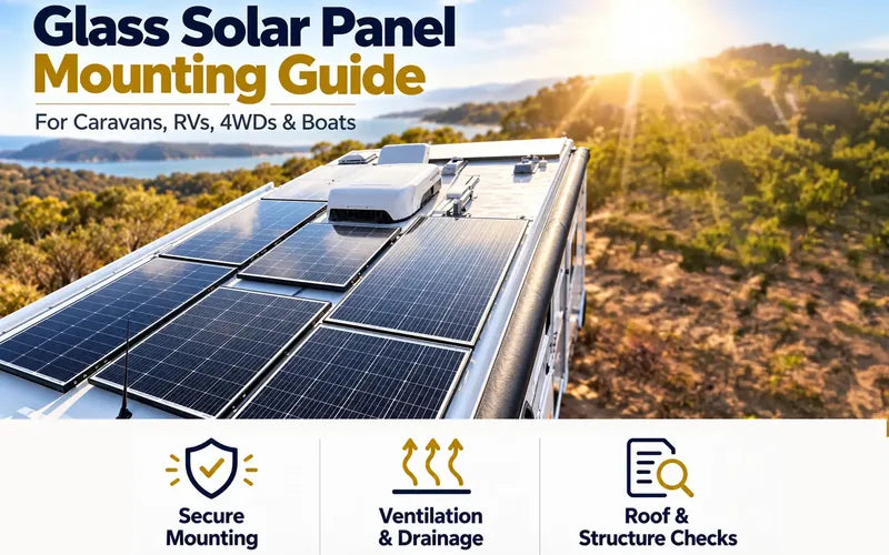
Glass Solar Panel Mounting Guide for Caravans, RVs, 4WDs and Boats
A framed glass solar panel is only as reliable as the way it is mounted. This guide covers mounting the framed glass solar panels we sell on caravans, motorhomes, 4WDs and boats.
Never assume one panel's mounting arrangement suits another. If your panel's maker has its own installation manual or warranty terms (in the box or on its website), follow them where they differ from this guide.

Every roof, rack and boat is different, and this guide can't assess yours. It doesn't replace a site-specific structural assessment or electrical design. The installer is responsible for confirming that the complete installation suits the expected wind, vibration, wave impact and operating environment, and that it meets the requirements that apply to the vehicle, vessel and location. Follow the instructions supplied with the brackets, adhesive, sealant, rack or canopy you use, and the roof, vehicle or vessel maker's limits. Use qualified tradespeople where required, and have electrical work done by a suitably qualified or licensed person where applicable.
Incorrect mounting or wiring can cause electric shock, arcing, fire, water or structural damage, or a panel coming loose from a moving vehicle or boat, resulting in serious injury or death. If you can't verify the roof structure, fixing method, adhesive compatibility or mounting arrangement, stop and get advice before continuing.
Contents
- Start with the exact panel
- Safety before work starts
- Plan the panel location
- Check the supporting structure
- Mounting basics
- Mounting methods
- Installation steps
- Final checks
- Inspection and maintenance
- Frequently asked questions
- Related products and guides
Start with the exact panel
Choose the mounting to suit the panel's size and weight, not its wattage. Before buying brackets or marking the roof, confirm the panel's overall dimensions, frame depth, weight and factory mounting-hole positions, measuring the panel itself rather than relying on another model's figures.

Treat the installation as one load path: wind and vibration pass from the frame through the brackets into the roof, rack or hardtop, and every connection must be strong enough. On a vehicle or boat, allow for wind uplift, braking, corrugations, wave impacts and heat cycles, not just the panel's weight.
Safety before work starts
- Plan safe roof access with a suitable platform and fall protection, keep people clear of the area below and secure tools and parts against falling.
- Don't work in rain or strong or gusty wind, or on a wet or very hot roof.
- Check the panel's weight and size, and have enough people to lift it under control.
- Wear gloves, eye protection and suitable footwear, and remove rings and watches before electrical work.
- A panel produces electricity whenever light reaches it. Cover it with an opaque sheet while working, use insulated tools and never connect or disconnect PV connectors under load.
- Never stand, kneel or put tools on the panel, or lift it by its junction box or cables.
- Handle the panel carefully: tempered glass resists loads across its surface but is vulnerable to edge knocks, twisting and point loads.
- Check the panel when you unpack it and report any damage to the seller before installing. Don't install a panel with cracked or chipped glass, a bent or separated frame, a damaged backsheet (the back of the panel), a loose junction box, damaged cables or connectors, or any other visible damage. A damaged panel can still be live in daylight, so keep people away from it until it has been assessed.
Plan the panel location
Draw a scaled layout of the roof, rack or deck before drilling, bonding or ordering parts, allowing room for brackets, cable bends, cable entry and future servicing.

A good location:
- stays within the vehicle's or vessel's permitted dimensions;
- avoids regular shade from air conditioners, vents, antennas, masts and racks;
- keeps an air gap under the panel and lets water and debris drain away;
- is clear of exhausts, flues and other heat sources, and of hatches, awnings, cargo and branches;
- leaves access for cleaning, inspection and eventual removal; and
- has a confirmed structural fixing point under every mounting point.
Roof edges and corners can see stronger, more turbulent wind than the middle of the roof, so don't copy another installation unless the panel size, roof shape and bracket spacing are comparable. For bifacial or glass-glass panels, also allow for rear clearance and protect the rear glass. This guide does not cover frameless panels.
Check the supporting structure
The roof skin alone may not carry the panel's loads. Caravan and RV roofs can be thin aluminium or fibreglass over framing, sandwich panels or empty voids, with wiring and plumbing hidden inside. Canopies, racks and hardtops can also have limited fixing zones.
Before installing:
- check the vehicle, roof or rack documentation for permitted mounting locations, and stay within the roof, rack, axle, payload and total-mass limits;
- find the structural members, and any wiring and plumbing, before drilling;
- look for corrosion, delamination, chalking, loose paint, soft spots and old repairs; and
- get written advice from the vehicle, roof or rack maker, or an engineer, if their documentation doesn't cover your arrangement.
An adhesive is only as strong as the surface under it: a bracket bonded to loose paint comes away with the paint. Sealant can't make up for a weak roof or a poorly supported fixing point.
Mounting basics
Use enough brackets, in the right places
Use at least four brackets on panels up to 1,500 mm long, and at least six on longer panels, adding a pair in the middle of the long sides. Panels in exposed positions, such as a roof edge or a boat, may need more support.
Brackets that bolt to the frame go at its factory mounting holes; corner brackets go at the corners. If the roof structure doesn't line up with the bracket positions, move the whole panel, or add a rail or backing that carries the load into the structure, rather than moving individual brackets.
Where a bracket has no factory hole, such as the middle pair on a long panel, drill only the holes for that bracket's screws, in the same flange as the factory holes, keeping the drill clear of the glass, the backsheet, the junction box and the cables. If your panel's maker has no installation manual of its own, this guide is its installation instruction, and drilling these screw holes as described here is part of the installation, not a modification. If the maker has its own manual, drill the frame only if that manual and the maker's warranty terms allow it; otherwise use only the factory holes and contact us before you start. Any other hole, enlarged hole, notch or cut is a modification that can weaken the panel and void its warranty. Don't clamp the frame anywhere else unless the panel's own manual gives clamping positions, and never let anything press on the glass.
Brackets must not shade cells or block the frame's drainage openings. Tighten bolts and screws evenly until each bracket is held firmly, using any torque the bracket, rack or fastener maker gives. Overtightening can distort the frame or load the glass, and an overdriven screw strips its hole and stops holding; undertightening lets the bracket move. Set the drill's clutch low or finish screws by hand.
Keep the panel ventilated
Framed glass panels must sit on brackets or rails above the surface, not be bonded flat. The air gap lets heat escape, keeps heat out of the roof, lets water drain and leaves room for cables. Don't seal around the panel's edges or fill the gap underneath, and don't reduce the gap just to make the panel sit closer to the roof.
Prevent corrosion
Most framed panels have anodised aluminium frames. Galvanic corrosion can occur where aluminium touches a different metal, such as a steel rack or a stainless rail, with moisture or salt present. Stray-current corrosion can progress much faster: it happens when DC current leaks from damaged, wet or badly assembled wiring and returns through the frame, brackets, chassis or hull. Only fixing the wiring fault stops it; a new bracket or more sealant won't.


- Isolate the mounting from the metal structure it's fixed to, such as a steel rack, rail or hull, not the bracket from the panel. Use non-conductive pads under the brackets and insulating sleeves or washers on their fixings, so no bolt or screw bridges the isolation. Seal the screws and bolts that go into the aluminium frame and brackets against water.
- Seal drilled holes, cut edges and scratches, and avoid joints that trap water.
- Don't rely on paint, powder coat or a thin adhesive layer as the only isolation, because coatings get damaged during tightening and movement.
- Keep the PV cables electrically separate from the frame and mounting, apart from any earthing the electrical design requires. Never use the frame, roof, chassis or hull as a return path for PV current.
- Assemble PV connectors with the correct tools, keep them supported and clear of standing water, and seal cable entries with covers suited to the cable and surface. Replace damaged, corroded or overheated connectors rather than taping or sealing over them.
On boats, the panel and its brackets must be isolated from all metal on the boat, including rails, arches, metal hardtops and the hull. Non-conductive brackets such as ABS help, provided no fastener runs from the panel or bracket into the boat's metal. The panel frame, DC negative, earthing, bonding system, shore power and anodes all interact, so don't change bonding or earth connections to fix panel corrosion without advice from a marine electrician. White powder, pitting, blistering or a voltage between the frame and the boat points to a mounting or wiring fault: isolate the PV system and have it inspected.
Use the right fasteners
Use corrosion-resistant fasteners, washers, backing plates and locking devices that fit the frame holes and brackets, and keep them accessible for inspection. They must stay secure under vibration without crushing the frame, bracket or roof. Use the locking method supplied with the bracket rather than adding extra ones; lubricants, anti-seize and thread lockers change how tight a joint ends up for the same effort.
Mounting methods
Brackets through the factory frame holes
Corner, side and Z-style brackets in aluminium or ABS plastic can be suitable where they fit the panel's frame and suit the supporting structure. Check the hole diameter, fastener clearance and tool access before buying.
The bracket-to-roof connection needs its own structural fixing and waterproofing; a well-fitted bracket doesn't make a poor roof fixing safe.


Bonded feet or brackets
Bonding avoids roof penetrations, but the adhesive then becomes a structural part of the installation. It must suit the bracket material, the roof and its coating, and the loads, temperature, UV, moisture and vibration it will see. Choose it from its documented suitability for that joint, not a general strength claim, and follow its full process for cleaning, primer, bond thickness and cure.
- Prepare and test the actual roof surface, including its coating, and never bond over chalking, oxidation, loose paint, polish, wax or dirt.
- Observe the cleaner and primer flash-off times, and control the adhesive thickness.
- Keep the vehicle or boat stationary and unloaded for the full cure time, and don't drive, tow or launch until curing and inspection are complete.
- Add mechanical fixings where the bracket instructions, the roof maker, the adhesive instructions or an engineering assessment call for them.
A sealant keeps water out; a structural adhesive carries load. Use a product documented for each job it does; some adhesive sealants are made for both.
Roof racks, canopies and marine hardtops
Check that the rack, canopy or hardtop can carry the panel's weight plus wind uplift and road or wave loads; a load rating alone doesn't show that. The rails must be straight and in line so the panel isn't twisted when tightened, with spans short enough not to flex. Rack clamps must not be able to slide along round or coated bars, and cables must be protected from cargo, sharp edges and branches.
Installation steps
1. Record the design
Note the panel model and serial number, mounting parts, fixing points and fasteners, adhesives and sealants, cable route and cure times. Photograph the serial number and rating label (the serial is on the front of some panels), keep the purchase invoice, and don't cover either with brackets, adhesive, sealant or paint. Keep a copy of this guide and the bracket, adhesive and sealant instructions with the vehicle or vessel records.
2. Mark the installation area
Mark the structural members, mounting points, cable entry and no-go zones, and check both sides of every hole before drilling. Stop if hidden wiring, plumbing or structure can't be confirmed.
3. Dry-fit everything
Position the brackets, rails, cable entry and panel before bonding or final tightening. The panel should sit flat without forcing, keep its ventilation and drainage gaps, come off again for service and stay clear of hatches, awnings and roof equipment.
4. Fit brackets that attach to the panel
Brackets that attach to the panel first, such as Z brackets, go on before it goes on the roof. Lay the panel face down on a clean, flat, padded surface, bolt them through the factory holes and drill any middle-pair screw holes there, not on the roof.
5. Drill the roof
Drill the fixing holes into the confirmed structure, clear of the edges of roof members and roof panels. For brackets already on the panel, set the panel in place to mark the holes, then lift it aside to drill. Clear away all swarf.
6. Prepare the surfaces
Prepare bonding surfaces only after all drilling is done. Follow the cleaner, primer and adhesive instructions exactly and within their temperature and humidity limits, without substituting products. Keep prepared surfaces clean and dry until bonding.

7. Bond and fix the roof attachments
Apply the adhesive as its instructions describe, then screw each bracket, foot or rail down with suitable fasteners and backing, and seal penetrations without blocking drainage. Brackets already on the panel go down with it, so have enough people to lift and place it. For bonded feet, control the bond thickness and allow the full cure.
8. Fit and tighten the panel
Where the brackets, feet or rails were fixed to the roof first, lift the panel onto them with enough people to support the glass and frame. Always start each bolt and screw before tightening any, tighten them evenly in sequence, and add witness marks so later movement is easy to spot.
9. Route the cables
Support the cables so their weight doesn't hang from the junction box or connectors. Use suitable solar cable, keep it away from sharp edges, heat, moving parts and pooling water, and secure the connectors so they can't flap or rub. Complete the electrical work using the Solar Panel Wiring Guide.
10. Cure, inspect and record
Keep the vehicle or boat stationary for the full cure time, and inspect the installation in good light before driving, towing, launching or connecting the system. Keep photos of the finished installation, a wiring diagram, the models of the controller and other connected equipment, any torque values used, adhesive batch details and electrical test results.
Final checks
Don't drive, tow, launch or connect the system until you have confirmed that:
- the exact panel model suits the application, and every bracket, fastener, adhesive and sealant is identified and compatible;
- the supporting structure has been verified and the panel stays within the permitted dimensions;
- the panel has enough brackets (at least six on panels over 1,500 mm long), the frame has no holes or cuts beyond the bracket fixings, and nothing presses on the glass;
- the panel sits flat and unstressed, with its ventilation and drainage gaps clear;
- the mounting is isolated from any metal structure it's fixed to (on a boat, from all metal on the boat), no bolt or screw bridges the isolation, and fixings into aluminium are sealed;
- there is no unintended electrical continuity between either PV cable and the frame, brackets, roof, chassis or hull;
- fasteners are evenly tightened and witness-marked, and bonded joints have fully cured;
- roof penetrations and cable entries are secure and sealed;
- cables and connectors are supported, protected from rubbing and clear of heat, moving parts and standing water;
- polarity, open-circuit voltage and any other required electrical tests have passed;
- no tools, swarf or packing are left on or under the panel; and
- the owner has the installation records and knows what to inspect and when (see Inspection and maintenance).
Then check for leaks using a method suited to the roof. Don't aim a pressure washer at seals, connectors or the junction box.
Inspection and maintenance
Vibration, salt, UV, heat and roof flex change an installation over time. Inspect it regularly, including while the vehicle or boat is parked or stored, and also after the first few trips, after rough roads, storms or impacts, and before long trips. Check boats, coastal vehicles and vehicles used on corrugated roads more often.
Look for:
- loose, missing or corroded fasteners and clamps, or movement marks around brackets;
- lifting, cracked or hollow adhesive and sealant, and signs of water getting in;
- cracked glass, a bent frame, delamination, discolouration or hot spots;
- dirt, leaves, bird droppings or other build-up on the glass: clean it off gently without abrasive cleaners, because build-up can cause hot spots;
- a loose junction box, strained or unsupported cables, damaged insulation, and loose, wet, corroded or overheated connectors;
- white powder, pitting or blistering where the frame, fasteners and supports meet, or damaged isolation washers; and
- blocked ventilation or drainage, or new equipment or cargo that shades or hits the panel.
If a fastener has moved, find out why before retightening it. If the panel rattles, shifts, lifts, makes unusual wind noise, has broken glass or damaged wiring, smells hot or lets water in, stop using the installation, keep people away and have it made safe and inspected. It can still be live in daylight. If you think the panel itself is faulty, photograph it in place, including the mounting and wiring, and contact the seller before removing it, unless it's unsafe to leave it where it is.
Frequently asked questions
Can I glue a framed glass panel directly to the roof?
No. Bonding the whole back traps heat, blocks drainage and loads the frame and glass in ways they weren't designed for. Mount it on brackets or rails with an air gap underneath.
Which adhesive should I use, and can mounting feet be held on with adhesive alone?
No single product suits every roof and bracket. Choose one documented for the roof material and coating, the bracket and the conditions, and follow its full preparation and cure process. Rely on adhesive alone only where the bracket instructions, the adhesive, and the roof maker or an engineer all allow it; many brackets are designed to be bonded and screwed.
Can any glass solar panel be installed on a caravan, 4WD or boat?
Not automatically. Check that the panel is suitable for mobile or marine use, and that its size, weight and mounting holes suit the structure available.
Will a marine galvanic isolator protect the panel frame?
Not necessarily. A galvanic isolator is intended to block small galvanic currents in the shore-power earth. It doesn't fix metal-to-metal contact in the mounting, damaged PV wiring or DC leakage, so find the actual corrosion path first.
Related products and guides
- Fixed and framed glass solar panels
- Solar panel selector table
- Solar panel mounting brackets
- Mounting brackets, adhesives and sealants
- Solar Panel Wiring Guide
- Solar cable
- Weatherproof cable entry covers
- Flexible solar panel mounting guide
Need help choosing mounting parts?
If you're not sure whether a bracket suits your panel, contact our team with the panel's brand and model before you start. For structural, electrical, marine bonding or vehicle modification decisions, use a qualified professional who can inspect the installation.