


REC 2Q BMS 16S Electronic Unit for 4-16 Cells Configurable Kit


Customise Your Purchase
REC 2Q BMS 16S Electronic Unit for 4-16 Cells Configurable Kit
We can ship worldwide and you can remove the 10% Australian GST that is included in our website prices. Please email info@solar4rvs.com.au for a product and shipping quote.
Note: The 2Q BMS supersedes the 1Q BMS.
Items supplied as part of the basic product (without any of the additional cost options):
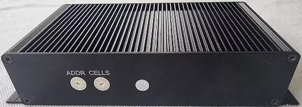
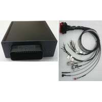
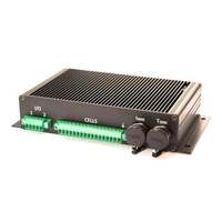
1. 2Q BMS Electronic unit
2. Wiring harness components which plug into the 5 connectors in the 2Q BMS:
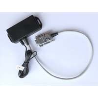
- "RS485-0" Connector: At present a connector is supplied with pins that is intended to connect to a Wi-Fi unit (please allow us to get some cables made up to go from this new connector to the REC WIFI unit)
- "RS 485 CAN T Cp" Connector with the following wires
- "RS 485-1" no wires on these pins
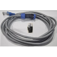
- "CAN" has a 0.5metre cable to a Weipu Series 13 connector (note that mostly inverters and controllers use an RJ45 connector for their CAN Bus, however as there is no industry standard pin-out for the RJ45 this leg of the CAN Bus cable is a separate purchase)
- "T" has a jumper wire
- "Cp" no wires on these pins
- "CELLS" Connector with the following labelled wires with a clean cut at 2metres length (for termination by the installer):
- 17 cell wires labelled as follows: "Cell 1-", "Cell 1+", etc to "Cell 16+"
- Power supply wires labelled: "Pack -", "Pack +"
- Pre-charge wire labelled: "Precharge"
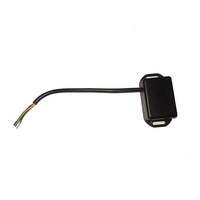
- "Isens Tsens" Connector with the following labelled cables each 2metres length
- DS18B20 digital temperature sensor x 2 (unlabelled)
- Shunt sense cable with 4mm lugs with 1 labelled "+" that attaches to the battery side of the shunt
- "Power symbol I/Os" Connector with 1 metre length cable and wire as follows:
- Power symbol: Cable to BMS on/off switch
- I/O wires labelled as follows:
- "OPTO RELAY IN", "OPTO RELAY OUT"
- "OC 1-", "OC 1+"
- "OC 2-", "OC 2+"
Key difference between the REC BMS and the “more typical” BMS
Note that the REC BMS is an entirely different class of BMS to the "typical BMS" used in a fully enclosed “drop-in replacement” LiFePO4 battery pack. The REC BMS does not have internal MOSFETS, as it is intended to be used with any size battery and any charge/discharge current as the load current only passes through an external passive current measuring shunt. Compare this with a “typical BMS”, eg Daly with electronic (using MOSFET transistors) switches where these are sized to suit the maximum charge/discharge currents.
The typical BMS will open the charge or discharge electronic switch if needed to protect the cells from over or under-charge. For small batteries and low currents this is arrangement is the best, however for large batteries and high currents the resistive losses in the MOSFETS means they run hot and the general rule of thumb is that mean time between failures of electronic devices halves for every 10°C rise in temperature; failure of a MOSFET typically causes the need to replace the whole BMS unit. This is where the REC BMS without MOSFETs becomes the preferable BMS.
Installation architectures
The REC 2Q BMS offers flexibility and can be used in various scenarios. Here are the different situations where it can be applied:
-
Managed Battery: In a managed battery setup, the REC BMS is connected to a hybrid inverter or energy system. The BMS communicates battery data, charge/discharge current, and voltage limits via the CAN Bus to the inverter or energy system controller (e.g., SMA Sunny Boy, Victron Cerbo GX). The inverter or controller then complies with the specified charge/discharge limits and relays the battery data to the user or monitoring system. This arrangement ensures that the battery cells operate within the voltage, current, and temperature limits set by the cell manufacturer. It also allows for proper cell balancing and reduces charge current during "topping-off" to the maximum charge voltage.
-
Standalone (Unmanaged) Battery: In situations where the BMS cannot directly control the charge or discharge voltage or current (e.g., when using basic chargers), relay contactors should be incorporated and controlled by the BMS. The BMS opens these contactors to prevent under or overvoltage conditions. Alternatively, if the chargers have a charge disable input, one of the BMS digital outputs can be used to control it and prevent cell overvoltage.
Additionally, there are combination architectures that combine managed and unmanaged elements. For example, when using a Wakespeed WS500 alternator regulator on the same CAN Bus as the REC BMS, the regulator will comply with the charge/discharge voltage and current limits set by the BMS. However, there may be other unmanaged chargers in the system, such as solar MPPT chargers, that charge based on their programmed charge profiles. In such cases, a relay contactor operated by the BMS may be required. If the REC BMS needs to open the contactor to protect the cells from overvoltage, there is sufficient time in the CAN bus protocol for the WS500 alternator regulator to take the alternator off-load before the BMS opens the contactor. This prevents a damaging voltage surge that could occur if the alternator was under load when the contactor is opened.
In summary, the REC 2Q BMS can be used in managed battery setups where it communicates with inverters or energy system controllers, ensuring compliance with charge/discharge limits and maintaining cell health. It can also be utilized in standalone (unmanaged) battery configurations by controlling relay contactors or charge disable inputs. Combination architectures are possible, where the REC BMS coordinates with other devices, such as alternator regulators, to ensure proper charging and protection of the battery cells.
2Q BMS Features:
- Suitable for battery packs between 4 – 16 cells (for 12V, 24V, 36V or 48V nominal battery packs or any number of cells between 4 and up to 16 cells (68V max))
- Suitable for standalone use, or with with built-in CAN Bus with hybrid inverters (see below for list protocols built-in and selectable by the installer)
- current measurement via separate external shunt (separate purchase if needed, or piggy-back the sense wires onto an existing shunt)
- 18-bit shunt current measurement (resolution 19.5 mA @ ± 500 A)
- single cell voltage measurement (0.1 – 5.0 V, resolution 1 mV)
- single cell - under/over voltage protection
- single cell internal resistance measurement
- State of charge (SOC) calculated from coulomb counting
- State of health (SOH) calculated from number of charge cycles
- Cell internal resistance calculated from ratio of voltage change and current change
- over/under temperature protection (up to 4 temperature sensors)
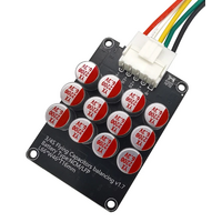
- passive cell balancing 4 Ω
- galvanically isolated user defined multi-purpose digital output
- internal DC opto-relay output
- programmable relay (normally open)
- galvanically isolated RS-485 communication protocol
- CAN Bus communication for managed batteries
- Galvanically isolated serial port communication for
- REC Wi-Fi unit for changing the settings and data-logging (optional accessory) or
- Users may connect the BMS into their system, eg home automation, industrial applications, remote monitoring, etc - error LED + buzzer indicator
- Remote ON/OFF
- Control pilot (CP) signal for Electric Vehicle Supply Equipment (EVSE)
- Integrated 25 Ohm pre-charge with adjustable time delay
- Integrated Real-time clock (RTC) with last 7 errors
- Watt-hour (Wh) counter
- ISO16315, ISO10133, EN61558-1, EN61558-2 and EN50498 compliant
Latest BMS manuals are available on the REC BMS website: https://rec-bms.com/battery-management-system/
Refer to https://www.solar4rvs.com.au/batteries/lithium/bms/accessories-for-rec-bms/ to see details of other components that you might want for your REC BMS system.
Ensuring Lithium Battery System Longevity
The Battery Management System (BMS) plays a crucial role in monitoring and controlling the individual cells within a battery pack. Its primary function is to measure the parameters of each cell and ensure their safe operation. Here are some key points regarding BMS and its operation:
-
Cell Capacity Variation: The capacity of each cell within a battery pack can differ, especially as the number of charging/discharging cycles increases. This discrepancy in capacity affects the time it takes for each cell to reach the fully charged voltage.
-
Fully Charged Voltage: For Li-poly batteries, the typical cell voltage for full charge ranges from 4.16 to 4.20 V, while for LiFePO4 batteries, it is around 3.5 to 3.65 V.
-
Voltage Imbalance: Since the cells have different capacities, they may not reach the fully charged voltage at the same time. Cells with lower capacity will reach the target voltage sooner, while others may lag behind. This situation can lead to overcharging of some cells when charging a series-connected cell pack without a BMS.
-
Negative Effects of Overcharging: Overcharging cells beyond the maximum allowed voltage will have detrimental effects on their capacity and longevity, reducing the number of charging cycles they can endure; this is also likely cause swelling of the cells.
-
Passive Balancing: To address voltage imbalances, the BMS employs a technique called passive balancing. It diverts some of the charging current from cells with higher voltage to power resistors. This process helps equalize the cell voltages within the pack. For those customers browsing and are looking for an active balancing BMS, for normal healthy cells there will be very little balancing required and therefore the energy loss in the balance resistors is inconsequential compared with active balancing (which is not entirely lossless anyway). If the capacity or self-discharge of a cell becomes unhealthy due to poor manufacturing quality or aging it is likely to eventually cause the BMS to trigger a cell voltage difference alarm alerting the user of the problem.
-
BMS Temperature Monitoring & cell balancing priority: When the BMS detects an excessive rise in internal temperature, it reduces the number of cells undergoing balancing. It prioritizes the most critical cells near the maximum BMS internal temperature setting to avoid exacerbating the heat issue.
-
Cell Temperature Monitoring: Digital Dallas DS18B20 temperature sensors are used for monitoring the battery pack's temperature. Each BMS unit can accommodate a maximum of four DS18B20 temperature sensors.
-
State of Charge (SOC): The BMS utilizes various factors such as battery pack current, temperature, and cell voltage to determine the state of charge. SOC represents the current energy level of the battery pack.
-
State of Health (SOH): The BMS assesses the state of health by comparing the current parameters of the cells with the parameters of a new battery pack. This evaluation helps estimate the battery pack's overall health and degradation over time.
In summary, the BMS is responsible for monitoring and controlling individual cells within a battery pack, ensuring their safe operation, and maintaining voltage balance. It also measures temperature to prevent overheating and uses various parameters to determine the state of charge and health of the battery pack
Visit REC BMS' Official Q BMS Webpage for More Details
(REC-2Q16S-BMS-KIT)
| SKU | REC-2Q16S-BMS-KIT |
12 Month Warranty


We'll keep you updated with the latest deals, so that you'll never miss out!