


Lithium Compatible Alternator Regulators
Minimum Price Maximum PriceLoading Products...


Alternator Battery Charging Background
1st Generation Alternator Regulators and Managing Temperature Rise
Situation Overview
In the first generation alternator regulators, the main objective was to limit the voltage output of the alternator. For example, it would charge the battery up to a design voltage of say 14.0V and maintain it at that level until the engine is turned off. The alternator's current output is determined by its design, engine speed, and the battery's capacity to absorb the current. Once the set voltage is reached, the current tapers off.
Temperature rises in the alternator case was never a problem for the vehicle owner as these alternators were designed to provide a high current for a short duration after an engine start to recharge the lead-acid battery. As the voltage rise at maximum amps to the set voltage of 14V was relatively quick the temperature rise in the alternator was not significant enough to be a problem. The current tapered off once the 14V was reached and thereafter the alternator current output varied to keep the voltage at 14v and to support basic electrical loads such as lights, wipers, and entertainment systems. This approach ensured that the alternator did not overheat.
Potential Issues with Additional Batteries
However, adding an auxiliary battery in the vehicle and/or a house battery in the caravan and directly charging them from the alternator could lead to prolonged high currents flowing through the alternator, causing overheating. Watch this video by Victron on more about alternators overheating due to battery charging. Furthermore, the use of LiFePO4 batteries exacerbates the problem, as they absorb high current for a longer portion of the charge cycle than the same Ah capacity lead-acid battery. Over the years the Ah capacity of house batteries has steadily increased and now tend to be much larger than vehicle batteries placing more demand on the poor alternator that was only ever designed to re-charge a vehicle battery after a starting the engine and supply power for vehicle only loads.
Potential Issues with Modified Voltage Regulation
In some cases, vehicle owners may attempt to increase the alternator voltage by adding a diode to the field winding circuit. This modification raises the upper limit of voltage regulation by the forward voltage drop of the diode. The purpose of this modification is often to compensate for voltage drop in long cables running from the front of the engine bay to a battery located at the back of a long caravan. However, this modification can worsen the situation, especially if the alternator's vents are partially blocked due to high mileage. This problem becomes particularly pronounced when charging the battery while the vehicle is idling at high temperatures.
2nd Generation Alternators and Vehicle Electronics
In the 2nd generation alternators, the voltage regulator is controlled by the vehicle engine electronics. The electronics are specifically designed to support the standard factory vehicle and contribute to reducing emissions. As part of this design, the voltage is lowered once the battery has been fully charged soon after the engine start.
Therefore, similar to the 1st generation alternators, the alternator system is not intended for, or suitable for, charging additional batteries. Modifying the system becomes more challenging due to limited access, warranty considerations, and the restrictions imposed by emission control legislation, which prohibit modifications to the vehicle systems.
Vehicle Alternator Regulators and Charging Challenges
Vehicle alternator regulators generally have a generic charging characteristic, which means they do not provide the specific charge characteristics and voltages specified by battery manufacturers for deep cycle and LiFePO4 batteries. To overcome the challenges mentioned earlier, a common approach is to use a DC to DC charger that is configured with the required charge characteristics and voltages for charging deep cycle or LiFePO4 batteries from the vehicle alternator.
DC to DC chargers offer the flexibility to set the maximum charge current output according to the size of the auxiliary battery and/or the capability of the alternator. This feature is particularly important in situations such as conversions of older vehicles like a 1970's VW combi van, where preventing alternator overheating is crucial.
It's worth noting that some DC to DC chargers have a bypass setting, which directly connects the input of the DC to DC charger to the output. In this mode, all the available current from the alternator is passed to the auxiliary battery until the voltage reaches a pre-determined voltage. After that, the bypass is opened, and the DC to DC charger resumes its charging function. However, it's important to consider that prolonged activation of the bypass mode could lead to alternator overheating, especially when charging a large LiFePO4 battery. Therefore, specific consideration must be given to the alternator's capacity, the type of DC to DC charger being used, and the potential charging time at maximum alternator amps for a fully drained auxiliary LiFePO4 battery.
Upgrading to an adaptive smart regulator for enhanced battery charging without over-heating and damaging the alternator
In cases where it is both possible and permitted, the original voltage regulator installed in the vehicle can be replaced with a more advanced and adaptable regulator. These upgraded regulators monitor the alternator temperature to prevent over-heating and offer selectable charge characteristics specifically designed to accommodate deep cycle and LiFePO4 batteries, which can now be utilized as the vehicle's main battery for engine starting and standard electrical loads. One notable company leading in this field is Wakespeed, offering the WS500 which has now shipped over 60,000 units.
The focus here is on the WS500, which features a CAN Bus interface that enables integration with a LiFePO4 battery management system (BMS). Through this interface, the BMS can set both the voltage limit and current limit for charging the battery. The significant advantage of this setup is that the BMS actively lowers the charge current while the battery cells are being balanced. Since the balance current is typically only a few amps, it is ideal to reduce the charge current to a similar level to avoid any voltage imbalances between the cells that could lead to runaway cell voltages and possible battery disconnects to protect the cells from over-voltage.
Comparatively, the older, less refined method of preventing cell overvoltage involved inhibiting the charger when the highest cell reached a pre-set voltage. However, this approach posed a problem: the voltage of an excessively charged cell would drop rapidly the moment the charging was halted. In such scenarios, a BMS that lacks control over the charge current can cause rapid cycling of the charging process, turning it on and off repeatedly while the cell balancer tries to balance the cells.
The REC BMS, which is programmed with user-defined limits for charge current and voltage, plays a crucial role in determining whether the charge current needs to be reduced for balancing and topping off the battery pack to 100%. It communicates these voltage and current charge limits, together with the present time voltage and amperage, to the WS500 regulator accordingly. Additionally, the WS500 monitors the alternator temperature to ensure the well-being of the alternator. If necessary, it will further decrease the current output to prevent overheating.
Adding a second alternator with WS500 alternator regulator
Where feasible this is the best system. In addition to the obvious benefits of keeping the original vehicle system unchanged and allowing the capacity of the 2nd (secondary) alternator to be sized for the Ah capacity and load of the house system, the voltage of the house system can be different to that of the vehicle and is especially valuable for large house systems. DC-DC chargers between the two battery systems, albeit at a much lower charging rate, can still be added to create a very high reliability solution.
Introduction to an Alternator Regulator
In very simple terms, an alternator can be described as a mechanically driven current amplifier. The regulator plays a crucial role by feeding a small DC current to the input field winding (rotor). Consequently, the alternator generates higher 3-phase AC currents in the output armature windings (stator), which are then rectified to DC and supplied to the battery and loads.
For example, the regulator could supply 2A to the field windings. At a particular rotating speed, the output could reach 50A DC, resulting in a gain of 25 (i.e., 50A output / 2A input).
.png)
Regulator Operation
The regulator in an alternator system is designed to continually monitor the battery voltage. It dynamically adjusts the field current, either increasing or decreasing it, to reach and maintain the set voltage set for the battery.
This means that the regulator acts as a controller, ensuring that the battery voltage stays within the specified range. By fine-tuning the field current, the regulator plays a crucial role in optimizing charging processes and preserving the health of the battery over time.
Compatibility of WS500 with Alternators
The WS500 regulator is designed to be compatible with a wide range of alternators. As the regulator is a separately replaceable part on any alternator, the WS500 can generally replace existing regulators. It's important to note that while the WS500 can be installed on various alternators, some adjustments may be necessary during the connection process.
When replacing the regulator with the WS500, attention should be given to the connection of existing wires to the WS500's wires. While this process may require some additional work, the versatility of the WS500 makes it a suitable upgrade for enhancing the performance and functionality of different alternator systems.
Suitability of the WS500 in a Vehicle or Boat
Alternators on older vehicles will have regulators would typically be set to charge to a voltage fixed somewhere between 13.3 – 13.8V and hold the voltage (you can see why some 4x4 drivers would insert a diode in the sense wire to trick the alternator to charge about 0.6 to 0.7V higher), but when maintenance free batteries were introduced the regulator would be set to charge to 14.0 – 14.5V and again hold the set voltage. The voltage regulation on these vehicles do not provide the recommended charge profile of AGM batteries nor any of the lithium based batteries, such as LiFePO4. It is best to use a programmable DC-DC charger to charge a secondary (house) battery.
A problem here is that house batteries have typically become much larger than the primary (vehicle) battery with consequential long charging times through a DC-DC charger. A work-around for this is to reverse the primary and secondary batteries, ie charge the house battery directly from the alternator and use a DC-DC charger to charge the vehicle battery from the house battery side. But when the house battery is in the same vehicle as the engine battery, eg motor-home, then it is possible to reverse the vehicle and house batteries and having the house battery connected to the alternator and the engine battery charged via a DC-DC charger from the house battery circuit. In this case it is necessary to replace the original regulator for a smart regulator for two reasons:
- To provide the correct charge profile for the house battery, preventing potential lifespan reduction.
- To add temperature protection on the alternator, preventing over-temperature issues by monitoring and adjusting the charge current accordingly.
A critical design issue that must also be addressed is to prevent a battery disconnect particularly when the alternator is charging the battery as a high voltage spike will occur which can damage the alternator diodes and any connected loads. A battery disconnect is referred to as a “load dump”. The reason for the voltage spike is that at the instant the disconnect occurs current obviously stops flowing through the disconnected switch with a consequence that the energy stored in the stator magnetic field starts collapsing with the energy being output as current that opposes the change in current, ie the current is initially equal to and in the same direction as the current that was flowing at the instant of disconnect which then decays exponentially. The voltage however is governed by V = -L dI/dt, ie the inductance * rate of change of current. This voltage ramps up rapidly and passes through the rectifier diodes and supplied to loads that are only designed to operate at the battery voltage. The voltage spike could go above 100V and take 0.4seconds to drop back down, by which time loads may have irreparable damage. Refer to Solar 4 RVs for solutions that need to be included in your system design.
More recent alternator regulators are linked to the engine control unit (ECU) which reduce the set voltage after a period of time to reduce fuel consumption and emissions. Alteration of these vehicles will likely cause an error and triggering, at the very least, an engine check-light.
A second alternator can be fitted to some engines and be fitted with a WS500 to charge a house battery system.
Installing a WS500
Retrofitting a 3rd party regulator like the WS500 requires the disconnection of the existing regulator (internal or external) and re-connection to the blue field current supply wire from the WS500. In general USA manufacturers wire the regulator on the positive side of the field, but European on the negative side of the field windings as shown below:
.png)
Load dumps - the "elephant in the room" with alternators & disconnectable lithium batteries
The "elephant in the room" with a system that includes an alternator and a lithium battery is called a "load dump". A "load dump" is the term used to describe a battery disconnect whilst the alternator is charging the battery; the disconnect is most likely to occur if the BMS decides to protect the battery by disconnecting it from the system, or the BMS could fail, or a protection fuse blows. Note that there is some ambiguity here, as "load dump" refers to the loss of load on the alternator specifically when the battery disconnects, rather than anything to do with the house loads that are supplied by the alternator or battery (depending on whether the engine is running or the battery is powering all the loads). It is specific to a battery disconnect because of two things:
1. loss of the stabilising effect the battery has on the voltage (a very low internal impedance is the property that provides the voltage stabilisation), and
2. (this is complicated) when the battery disconnects there's an instantaneous drop in the current output by the alternator stator which causes the energy stored in the magnetic field in the inductive windings of the stator to oppose the change in current (Lenz's Law). This stored energy is converted into current that flows in the same direction as the current prior to the disconnect and flows through the alternator rectifier and any circuit still connected to the alternator. The current drops exponentially at a rate determined by the time constant of the inductive stator. But in tandem with the release of the stored energy as current the voltage rises (Faraday's Law) almost instantaneously because of the collapse of the magnetic field and the peak can be high enough to cause the current to arc across contactors degrading them and also damage electronic components in some of the powered equipment. The voltage peak could in theory be 100's of volts and the duration could be up to 0.4 seconds. The alternator regulator by itself cannot prevent the BMS of a lithium battery from disconnecting the battery and therefore is not able to prevent damaging spikes from occuring, however there are some system design features that reduce the likelihood of a disconnect occuring and/or minimising the voltage spike so that damage to the alternator and loads is avoided.
Deactivate regulator before battery disconnect
1. Use BMS with CAN Bus: this is the best way to control the battery charging as the BMS will limit the charge current during balancing and can reduce the charge current as the cells approach the end of charge voltage, thus lowering the possibibility of a cell-over voltage disconnect. If something goes wrong and a cell exceeds the threshold at which a battery disconnect will occur the BMS will provide sufficient time for the regulator to set the field current to zero so that the battery disconnect can occur without a spike. Similarly as the battery is discharged the alternator will be deactivated before the battery disconnects to protect the cells from too low a voltage. A voltage surge suppression device should also be included to further protect the system as the BMS could fail resulting in an uncontrolled battery disconnect.
2. Use BMS with discrete control ouputs: the BMS can be set to disable these control outputs so that the regulator sets the field current to zero in sufficient time before a battery disconnect occurs. This is not as good as 1) as the charging current could be quite high during balancing and approaching the end of charge voltage which increases the possibility of the higher cell(s) shooting over the disconnect voltage threshold. As with the CAN Bus BMS a voltage surge suppression device should also be included to further protect the system as the BMS could fail resulting in an uncontrolled battery disconnect.
Reduce likelihood of a battery disconnect
3. Set charging voltage to lower, safer level: setting the end of charge voltage to a lower level reduces the possibility of an over-voltage disconnect. Note that balancing cells is not feasible with most BMS's below 3.45V for LiFePO4 cells as it is only above this voltage that imbalance becomes visible by differences in voltage. As there is no guarantee of an unexpected disconnect a voltage surge suppression device should also be included to further protect the system.
4. Have multiple independent "drop-in" batteries in parallel each with its own BMS the idea being that at least one battery is connected at all times. However, many causes of disconnect could be common to all paralleled batteries, eg high cell voltage, short circuit, etc, could cause all the batteries to disconnect near simultaneously. Another downside to this is that you may not be aware that one (or more) batteries have disconnected whilst at least one remains connected.
Clamp voltage spike
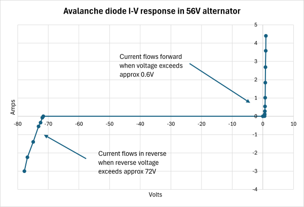
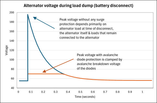
5. Ensure avalanche diodes are used in the alternator rectifier. If unsure, you will need to check the specification for your alternator as recent alternators are likely to have them, but not older units. In normal operation avalanche diodes operate the same as conventional diodes by blocking current in the reverse direction, but for an avalanche diode when a disconnect occurs and the voltage spikes the avalanche diode conducts current in the reverse direction limiting the voltage spike to a much lower controlled level and without damage to the diode, unlike a conventional diode rectifier that is likely to be damaged unserviceable. The shorted current then flows through the recitifier and stator windings until the voltage subsides back to voltage limit set in the regulator. This at the very least protects the alternator rectifier from damage from a load dump, and limits the peak voltage sent to the loads. An example of the diode DC characteristic in a Bliss 56V, 200A alternator is shown below:
The voltage response of an alternator to a load dump without and with an avalanche diode rectifier is shown below: This is the dynamic response and in this case the peak voltage will be clamped to around 72V.
6. Install a secondary Balmar or Sterling "Alternator Protection Device" which basically do the same thing as the avalanche diodes in the alternator, ie they short current from the positive rail to ground thus limiting the voltage spike to a safe voltage. These are always recommended in addition to any of the previously stated methods as they also protect from voltage spikes regardless of the source of the spike, eg some lightning induced spikes.
2nd battery that cannot disconnect
7. Have a smaller second battery, eg. lead-acid, wired in-circuit specifically so it absorbs the short burst of power during a disconnect preventing the voltage spike occurring. The second battery could be a "sacrificial" battery just for the purpose of absorbing the spike energy from a disconnect, or could be a start battery charged via a FET based charge splitter, eg Victron Argofet; noting that the battery will be subjected to the same charge profile as the house battery.
We'll keep you updated with the latest deals, so that you'll never miss out!